ART PRO MPA 2 - XLR chanel 1 is not working

mindw0rk

New member
Hi Guys!

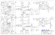
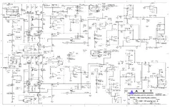
I have got ART PRO MPA 2 preamp and XLR input on channel 1 is not working, the DI (HiZ) of the same channel is working, chanel 2 is ok, I have attached a schematic from the similar thread... I am not sure where I shall look for the issue, I can't read the schematic, is there any chance you can point me out where I shall look for?

Thanks!
 

Attachments

  • Art Pro MPA II Schematic-3.png
    Art Pro MPA II Schematic-3.png
    480.1 KB · Views: 30
See if the place where you found the schematic has the other 3 pages as this is 2 of 4.
Then we'll see if we can point in a direction?
Congratulations BTW, you have exactly one more page than I ever got from ART. They would never even reply to me.
I stopped purchasing anything from them as soon as I had a failure (preamp) and they wouldn't reply.
Here is another one I've managed to find:
 

Attachments

  • Art Pro MPA II Schematic-Output Section.png
    Art Pro MPA II Schematic-Output Section.png
    617.5 KB · Views: 30
Here's what I have on the ART MPA. It is listed as the Gold version, so I don't know how similar or different it is from the standard DMPA II.
One thing you should consider is whether any differences between the two versions are significant to your service questions.... it's kind of hard to do without having complete schematics for the model in question.

Starliner
 

Attachments

  • ART MPA Gold - Schematic - 9-21-21.pdf
    293.8 KB · Views: 25
Last edited:
If this is the correct diagram, you have two identical circuits, one for the right input, one for the left. The balanced input also has the phantom supply. Are you using the phantom power when trying the "dead" channel? The 48 volts for this will be the same supply for each half but it does have to go through Switch 14 (if it is the dead side). Does the channel work with a dynamic mic? (not requiring phantom power)

The reverse biased small signal diode pairs d206 and d207 and the other set d210 and d211 keep the input signal balance in between circuit's power supply +- 15 v . If you have a digital volt meter (you don't need a scope) you can verify the DC voltage drops across these (not breaking down) and since the other channel is working get can check against it.

WARNING ***** The tube section will have a high voltage power supply ****** If you don't know what you are doing, read no further and take it to a electronics bench technician or buy a replacement *******

If you are familiar enough with your digital multimeter, you can power down and check each the transistors (2n4401 and 2n4403) conductance. Base to emitter forward baised, base to emitter reverse bias (blocking), no shorts across any pair. Again since the other side is working you can compare to it even with the transistors "in the circuit."

Let us know your capabilities with a multimeter?

If it's nill, seek out a local bench technician that can perform these basic checks.

The individual parts are relatively cheap, the tech time will be much higher but an experienced tech will identify the issue quickly and swap out parts quickly.

I'm only guessing here by the traditional parts and design without seeing it that they aren't using SMT (surface mounting) so part replacement should be easy.

Cheers,

Tom
 
Thanks Tom, guys and girls for the help!

You have mentioned the following diods:
"d206 and d207 and the other set d210 and d211...." I found them on the channel 2, the schematics corresponds to the right input and output... so in my case I should be testing: D204 D205 and D200 D201 located on the broken Chanel 1?

I did not get you with the transistors spec., there are sevral instances of the 2n4401 and 2n4403 transistors which corresponds to the different Q200, Q201... etc.. (again, I am talking about Chanel 1 - the left I/O).

I do not have a condenser mic, I own a dynamic one - SM57, the XLR input 1 is not working with it. I do not know how to use a multimeter, but I have one with me. I am planning to buy diods which corresponds to the ones I have mentioned above. My plan is to replace them - one by one and see if it does the trick. Do you think it will work that way? I could do the same with transistors...

Attached a photo just in case:

https://drive.google.com/file/d/17gVMLGshYpjHA9j-wSSthjjgYdqORPWp/view?usp=sharing

Best!

mindw0rk
 
Ques 1 ;"You have mentioned the following diods:
"d206 and d207 and the other set d210 and d211...." I found them on the channel 2, the schematics corresponds to the right input and output... so in my case I should be testing: D204 D205 and D200 D201 located on the broken Chanel 1?'

Answ 1; If channel is what they call the left, then yes.

Ques 2; "I did not get you with the transistors spec., there are sevral instances of the 2n4401 and 2n4403 transistors which corresponds to the different Q200, Q201... etc.. (again, I am talking about Chanel 1 - the left I/O)."

Answ 2; Q200 to Q213 are all associated with that channel. Any one of those could be failed?

Ques 3; "I do not have a condenser mic, I own a dynamic one - SM57, the XLR input 1 is not working with it. I do not know how to use a multimeter, but I have one with me. I am planning to buy diods which corresponds to the ones I have mentioned above. My plan is to replace them - one by one and see if it does the trick. Do you think it will work that way? I could do the same with transistors..."

Answ 3; If you are planning on what I used to call "shotgunning it" by replacing all the active components in that channel then have a lot of diodes, transistor and an op amp (U200) to replace. You'll have to look at it and read it's part number.

Ques 4 ; "Do you think it will work that way?"

Answ 5; That is most likely totally dependant on you soldering skills.
You have to be able to de-solder the old ones without destroying the surround PCB foil, then solder in the new ones without cooking them.

It would be a lot more practical to find someone who can show you how to use your multimeter to isolate the problem component.

Cheers,

Tom eh
 
This is frankly crazy. You don’t know how to use a meter, but instead of learning basic things you want to start removing soldi state devices with a soldering iron? How did you learn to solder but not to use a meter? You will destroy things. You will find a diode with poor printing and without the meter put it in the wrong way. The meter allows you to compare. If you have two circuits the same, you can measure values and compare. You can then see differences. You can also, if you are safe, work on the device powered up. Turn up a good channel, and turn up the bad one, then with a metal screwdriver or probe, you tough the mic xlr connection to the lib on pin 2, you will hear a buzz, same on 3. Try the. The failed channel and it will be silence. Then on the good channel, follow the pub tracks and follow the buzz. Good and bad channels at some point, join up. You will find the failed channel suddenly starts to buzz at one point, but if you head towards the xlr, it stops. You are then in the right area. Compare the same point in the good channel. This is when you might want to examine that area carefully. If it’s an op amp, and the third pin buzzes on the good channel but doesn’t on the bad one, you’re then right to consider swapping just that one as an experiment.

you can not fix faults randomly. You MUST be systematic and learn to read that meter!
 
Ha, ha,

Was I too polite Rob?

So MindWork what you indicated is;

1. You don't know how to use the a multimeter so you won't know how to test anything in the circuit.
As I said earlier "It would be a lot more practical to find someone who can show you how to use your multimeter to isolate the problem component."

2. You haven't indicated your soldering skills but if you have learned the basics as Rob said, we doubt that your soldering is up for the job?
As I said earlier "You have to be able to de-solder the old ones without destroying the surround PCB foil, then solder in the new ones without cooking them."

Rob has stated "if you are safe, work on the device powered up."

I'll stick with "WARNING ***** The tube section will have a high voltage power supply ****** If you don't know what you are doing, read no further and take it to a electronics bench technician or buy a replacement *******"

I didn't go in that direction at all since you haven't shown any familiarity with electronics, you won't know what "is safe" such as where that 150 Volt supply is for the tube.

Also without going into too much detail "shotgunning" is usually reserved for intermittent problems on critical equipment. In other words you can catch the component that's intermittently failing while it's on the bench but the section of the circuit that is failing is know or at least an educated, logical view points to it.

So crazy is; (as in lack of visible logic)

1. The chance of success replacing any one component is low, let alone that many.
2. Not knowing the basic characteristics of the components, how to use the multimeter, or how to trace out the circuit.
3. Not being able to see what active components are in the circuit that you are interested in when you are looking at the schematic.
4. The total cost of quantity of components suggested versus the individual cost of the one failed component.
5. Seeing how simple the circuit is and knowing that a bench tech or anyone with experience would be about 10 minutes to get it operational (having parts on hand, and less assembly time)

I don't want to discourage you from learning how to do this, but I don't give a newbie free range in my shop for several reasons.
You wouldn't give someone a chainsaw without training them would you?

Cheers,

Stay well everyone.
 
Back
Top