Ampex MM-1000 Story...

Productive evening as far as Matilda is concerned...

  1. Got the tape path cleaned up (again)... :o
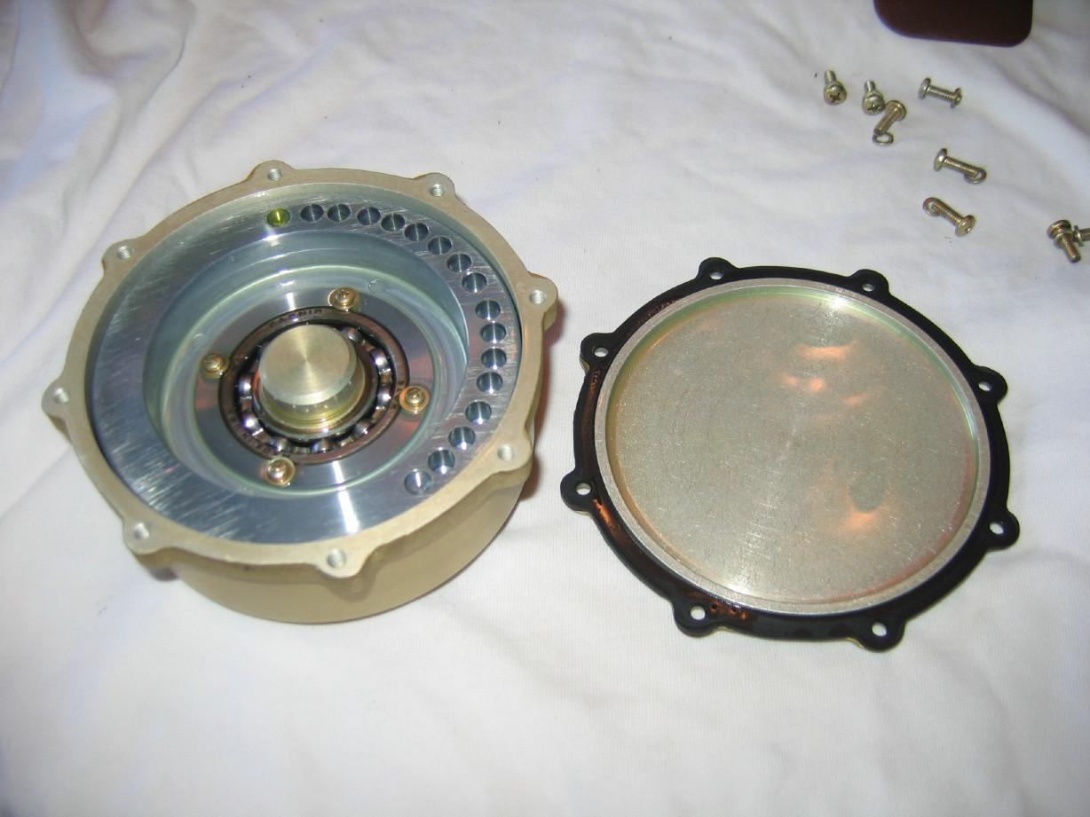
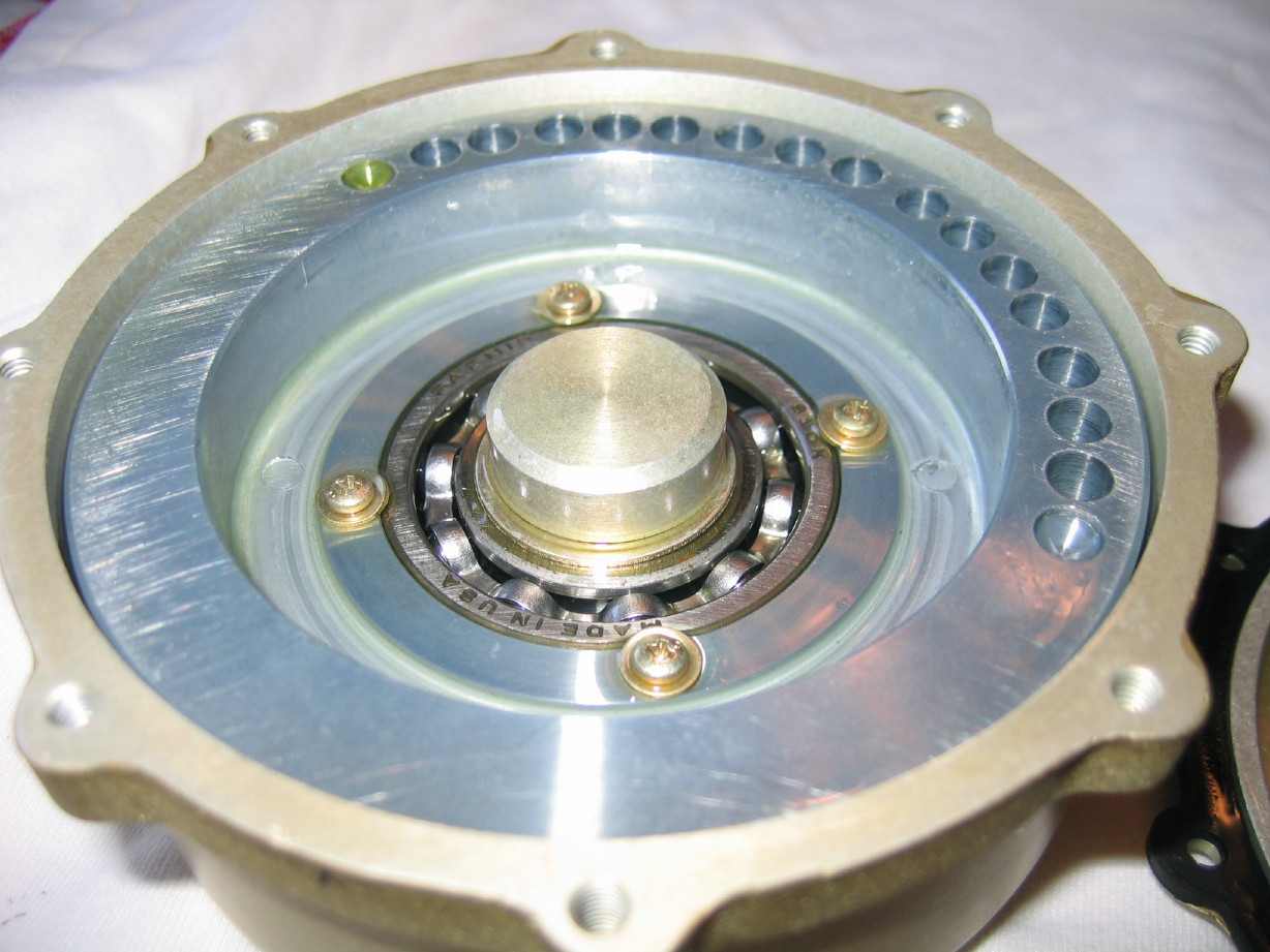
  2. Got the two rolling guide bearings replaced...no more crazy noises during fast-wind.
  3. Got the brakes re-adjusted. I was having trouble with the high adjustment on the supply reel (provides braking in the counter-clockwise direction)....couldn't tighten the springs down enough to get the right resistive force. Then I saw it...for all the over-engineered facets of this machine I think the plates to which the brake solenoids and one end of the brake bands anchor could have been a little thicker. Looks like after 40 years sharp impact from the solenoids actuating the plate was just slightly crowned. That was enough to allow just enough slack in the brake band that it couldn't be properly tensioned up. Bent it straight and it works great now. Just took a tiny bit...sensitive adjustment.
  4. Degaussed the entire tape path which took a bit. My Han-D-Mag was getting HOT!
  5. Set all the tensions (PLAY holdback and takeup tension, FFWD holdback, REW holdback and PLAY boost torque). This is a relief as I've been dreading this a little bit. There are no instructions for setting these things using a Tentelometer...its all using spring guages with cords wrapped around reel hubs. I was picturing a dreadful mishap involving a spring guage going *thwap*thwap*thwap*...wasn't too bad and didn't take long. Things were pretty close but there was room for tweaking. Now that I have a baseline using the factory method I can measure the current tape tension using my Tentelometer and then use that to check in the future. The other trick is that Steve Puntolillo suggested setting playback tension using an amplitude droop method: reproduce 16kHz on a test tape. Reduce the playback tension until there is an amplitude droop. Find the tension at the knee point and then increase tension by 1oz and call it good. It'll be interesting to see how close the factory method got the tension to this amplitude droop method. Another day...have to bake my MRL...have to find the snackmaster. We bought one about 6 months ago. Haven't used it yet.

Still having a problem getting the transport into PLAY mode with the switch on the control panel. Not all the time but when it does it stays that way for awhile. I can get it to play by manually by pushing on the proper relay in the relay box and the relay holds so there is holding voltage, just not the initial voltage to energize the coil. I'll trace that down later. For now its not that big a deal to have to reach around behind the machine and push on the relay.

Also was able to listen back to Sunday night's recording. Hard to tell through just one ear of a set of headphones (still working on a summing mixer to rack up in the MM-1000), but I WILL say it is all there (a full reel's worth) on one track and there is no funkiness/dropouts/warbling, etc. Sounds like it did in the room which is to say its overpowering in the mid-range, and its obvious I need to work on my shofar technique.

I'll try to get an mp3 of that up at some point.
 
Urg...

I'm having trouble with the reel table heights when using precision reels with the thick flanges...This may be a side-effect of crafting and installing the new reel table corks but that was necessary...the old ones were clearly no longer in a condition to effectively grab the reel. The new cork material is thicker than the old simply because the old had been compressed and had become hardened and brittle due to over 40 years of aging and being squashed under reels of tape. Anyway, the tape rubs just slightly on the bottom flange especially on the takeup reel when using the precision reels. The reel table heights are fixed on the MM-1000...the only way to address this is to place shims between the motor and the transport plate. :mad:

Also, I'm gonna have to break down and have the pinch roller re-rubbered. Its functional but the surface has lumps in it and it is glazey too. Bearings need replaced anyway...wish I had a spare, though Terry has a pretty quick turnaround.
 
Wouldn't it be simpler to just find some thinner cork?

Good luck!

Cheers! :)

Well, you'd think wouldn't ya? BUT...it is already a thin material that is special for this application...it is fabric-backed and the cork is of a specific quality and density. It is the same material originally spec'ed by Ampex. That's what's confusing...it *should* work. The other thing I need to check is to confirm that the fixed guide right before the takeup reel is at the right height...it is possible that THAT needs to be shimmed...need to see how the tape is riding on the counter-roller and such...maybe there is a shim washer that is missing. I also found that the post on the SUPPLY tension arm was leaning. I straightened it. Maybe the takeup side is doing the same thing which could potentially skew the tape.

Bottom line is that I do not want to mess with the material on the reel table, and I'd have to remove the motor to do that anyway as the reel lock attaches from underneath and the access gap in between the backside of the table and the face of the motor sits right at the same level as the transport plate so you have to drop the motor out to get an allen wrench to the screws that hold the reel lock to the table (and the reel lock needs to come off as part of the process of cutting the bulk material).
 
Is there enough thickness in the cork to just grind it down to the desired thickness, in place...like by just applying a sanding block directly onto/into the cork as the reel motor turns it. And then just have a good shop vac in place to suck up the dust as it sands down to the right thickness?

Cheers! :)
 
That's certainly an idea, but I'm not gonna do that. The cork material is Ampex spec. If something is off its not the cork.

I'm going to do some checkingon the guide heights...I'm also going to check the thickness of the reel spacers I had made (recall that the reel locks are for 2" reels...when loading 1" reels there are aluminum doughnut-shaped spacers one below and one above the reel). IIRC they are identical to the one stock spacer that came with the machine. It is possible those are sized for standard flanges. If that is the case I may have a second set made up for precision reels. It'd be worth it. I have another part I'd like to have made too to be able to use the 1" rotary guide from my parted out 440-8 as a rolling guide ahead of the head cover on the MM-1000...I'd then use the free rolling guide in place of the static guide just in front of the headblock. I might be able to save a bit of expense if I have all of that done at once.

The whole path is precision-fixed and references the transport plate...Ampex went to extreme considerations to stabilize the transport plate and to ensure it is true, so I don't want to mess with the motors and corks...that's why they aren't adjustable, because they shouldn't need adjusting and if something ain't right I need to look elsewhere for the solution...going to measure a 2" precision hub thickness tonight and then compare the 1" precision hub plus two spacers and see if they are equal. The sum of the latter should equal the dimension of the former.
 
Last edited:
That's certainly an ideàbut Izm not gonna do that. The cork material is Ampex spec. If something is off its not the cork.

I'm going to do some checkingon the guide heights...I'm also going to check the thickness of the reel spacers I had made (recall that the reel locks are for 2" reels...when loading 1" reels there are aluminum doughnut-shaped spacers one below and one above the reel). IIRC they are identical to the one stock spacer that came with the machine. It is possible those are sized for standard flanges. If that is the case I may have a second set made up for precision reels. It'd be worth it. I have another part I'd like to have made too to be able to use the 1" rotary guide from my parted out 440-8 as a rolling guide ahead of the head cover on the MM-1000...I'd then use the free rolling guide in place of the static guide just in front of the headblock. I might be able to save a bit of expense if I have all of that done at once.

The whole path is precision-fixed and references the transport plate...Ampex went to extreme considerations to stabilize the transport plate and to ensure it is true, so I don't want to mess with the motors and corks...that's why they aren't adjustable, because they shouldn't need adjusting and if something ain't right I need to look elsewhere for the solution...going to measure a 2" precision hub thickness tonight and then compare the 1" precision hub plus two spacers and see if they are equal. The sum of the latter should equal the dimension of the former.

Got it! ;)

Cheers! :)
 
:confused:

/brains_explode

Heheh...

What I'm saying is that spacer + spacer + 1" precision hub should be the same as the 2" hub.

Annnnnnnnd...IT IS!

At least ridiculously close.

The spacers are 1.005", the 1" hub is 1.210". That's a total of 2.220" for the trio (2 spacers and the hub). The 2" hub is pretty much 2.220". So that's not the issue. Time to go sniffing around other possibilities. Isn't this fun?? :D
 
I/O panel repairs...

So I'm diving into this one...its not taking priority per se but its going to become an increasing hassle if I don't do it at some point.

I'm talking about the 2U panel housing the 16 XLR jacks in the back. This one:

IMG_6850_1_1.JPG


IMG_6853_3_1.JPG


Doesn't look too bad in these pictures...a little cleaning up would be good sure, but that's not why I just clipped all 48 soldered wires going to these jacks...

At least 1/3 of those solder joints were on their last legs, or rather the wires were...hanging by a thread. For my audio tests I literally shoved some of these together just to ensure better conductivity. So I'm going to re-strip the wires, suck the old solder and wire remnants out of the cups and burn it back together, but not before addressing a couple other things...

Look at this (horribly blurry) pic of the face...What's missing??

IMG_6851_2_1.JPG


Okay...I'll tell ya: notice that on the top row of XLR-F jacks there are no release tabs...that's right...every single one of these has had the tab busted off which means that once you plug in an XLR cable to these jacks you have to unlock it from the back side of the jack to get it to release. Not convenient. I think I have enough of the tabs in other surplus jacks laying about to repair these.

I have a hunch that the event or events that led up to the jacks being "tab-less" probably also had something to do with this:

IMG_6855_4_1.JPG


That's not an optical phenomenon from the camera lense...that panel is really bowed like that.

So, straighten and clean the panel up, clean up the jacks, install lock release tabs, and renew the solder joints.

No pressure to get this done because all audio connections CAN plug directly into the electronics modules...the I/O panel is a convenience port for permanent installs. It'll be nice to have it fixed up and back in but tracking can still occur with this out of the machine.
 
Wow!!! Thats quite the "wow" in that panel.Wonder how it got to be like that.
Keep the story rolling Cory.
 
500~700lbs on the move carries quite a bit of momentum.

The power connect panel was similarly bent. At some point I imagine that this machine was rolled too close to a wall with the power cord and an audio snake hooked up.
 
Measured the thickness of the stock reel spacer that came with the MM-1000 and it is within +/- 0.001" of the thickness of the spacers I had made up.

Next I'm going to start measuring the guide heights from the transport plate to the lower edge of each guide and see if I can find any discrepancies...also going to look for any skewed guides that might be kicking the tape up or down...might seem to be a stretch but even a pinch roller-to-capstan shaft mis-alignment could cause the tape to skew up or down after that last static guide and I'm seeing a problem in FFWD where the tape drops down on the counter-roller so something is not quite right yet.

Got 8 of the 16 XLR jacks cleaned of wiring remnants and excess solder. Tedious, but its amazing how well these old jacks handle the heat...absolutely no melting or distorting of the insulator that holds the pins and solder cups...classic Cannon XLR jacks.
 
The bottom of the tape guides are a nice 1.500" up from the surface of the precision transport plate, and this includes the static guide on the output side of the headblock after the tape counter roller, so that's not the problem with the tape rubbing on the reel. Still need to check on whether or not any guides or pins are skewed. What I DO know is that a precision hub measures about 1.210"...A standard 3-screw hub/flange set measures about 1.194"! :eek: 
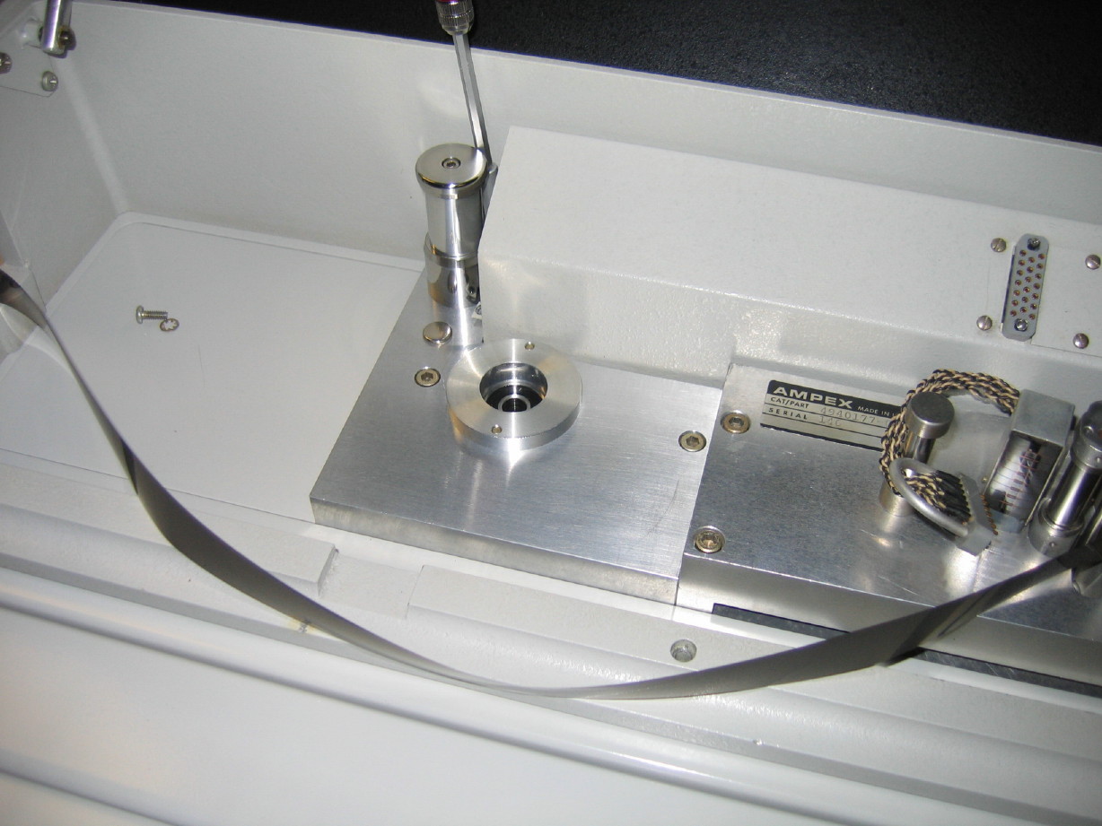
That's about 0.016" difference. Sound small? Its enough to answer why I have trouble with a precision reel and not a standard reel (as the whole reel sits higher and the flange is thicker on the precision 6-screw reel). Couple more measurments to do but ultimately I may be looking at having another pair of spacers made up that are slightly thinner to use underneath each reel when using precision reels.
 
Okay...so I'm putting the reel height spacing issue on the back burner for the moment as I have a more immediate issue.

The tape tension is varying on the transport supply side of the capstan (just before the erase head, which is where I've been instructed to place the probes).

When I put the Tentelometer probes on the tape the tension varies from about 9 to 10 ounces and the needle on the Tentelometer is jittery. I can (every few seconds) hear a drop in the audible pitch of the tape going through the tape path, and then it'll pop back to where it was. I can see this as a change in tension on the Tentelometer; the change in sound corresponds with a change in tension of about 0.5 ounces.

When I place the Tentelometer on the takeup side of the transport aft of the capstan it is wonderfully smooth and steady at 6 ounces or so.

Things I have done:

  • Checked to make sure the capstan shaft is spinning true (and boy is it ever...dead steady)
  • Checked to see if the fluter idler roller is spinning true (and it has about 0.001" runout)

Maybe it is a pinch roller issue? My pinch roller spins smooth but the bearings are a little rough. As I've mentioned elsewhere (I think) there are imperfections in the pinch roller surface...I can feel them with my finger... Hard to see but its not a nice smooth grippy rubber surface. It is somewhat hard and glazed. I don't understand how that could cause variation in how the capstan drives the tape though as all the pinch roller does is press the tape to the capstan shaft...I've asked this question in a related thread:

https://homerecording.com/bbs/showthread.php?p=3421947#post3421947

Maybe its tape deck 101 but its always baffled me why it matters whether or not the pinch roller is hard or smooth and matte in appearance vs. shiny.

Thoughts?
 
Well, tape is kinda slippery, both on oxide and back coating. A shiny pinch roller means a pinch roller that is less porous, more hard, more slippery. slippery surfaces on slippery surfaces = issues.

Seems this thing is built like a tank, so rubber parts are your weakest link.
 
Well, tape is kinda slippery, both on oxide and back coating. A shiny pinch roller means a pinch roller that is less porous, more hard, more slippery. slippery surfaces on slippery surfaces = issues.

Seems this thing is built like a tank, so rubber parts are your weakest link.

Muck, I get your point, but see my counter-point in the related thread linked above. I'm over-thinking it as usual but its always been one of those things where I furrow my brow a bit when it is said that the tape slips because the rubber isn't as grippy, and I'm thinking the tape slips because the roller is no longer soft enough to effectively and consistently mate the tape to the capstan shaft. Hm...

Okay, so I did a bunch of stuff tonight.

I decided it was time to replace the bearings in the reel idler because I knew they were mediocre and after seeing the instability in the Tentelometer today I decided it was time to start picking off suspects. Plus, it won't be at all easy to get the thing out once the lower racks get populated so there ya go. Pulled the flywheel, slid the roller out, unbolted the plate from the transport, removed the bearing housing from the plate, warmed it in the oven, made sure I didn't get any old cheese from the oven mitt onto the housing when I took it out, slid the old bearings out and slid in the new and let it cool.

The old bearings were worse than I thought. Noisy in a grindy way, and sloppy loose.

Here's the roller and bearing housing with the new bearings sitting on the plate...the rolling guide says "Hey I've got new bearings how about you??" "Yep!" says the reel idler. Okay...its late...

IMG_6862_4_1.JPG


Aaaaaaaand here it is back in the transport ready to receive the roller:

IMG_6863_5_1.JPG


Spins much better now.

I also got the I/O panel straightened, cleaned and applied the polish. I'll buff it out later.

Also, related to that, I trimmed all the cabling for the XLR jacks and cleaned the muck off of them. Ready to strip and solder, once I get the jacks cleaned up and repaired.

Okay, back to the reel idler assembly for a bit...So I wanted to have a look inside the flywheel. Remember this is a viscous assembly. There is a flywheel inside the flywheel housing that can freely spin inside, but the housing has a special oil in it and once the housing gets spinning, centrifugal force throws the oil up along the walls of the housing, and that grabs the inner flywheel. So it is light and turns easily when tape is just starting, but then it gets heavy as the heavy inner flywheel gets dragged into the game. This arrangement, the mass coupled with oil, provides impedance and flutter damping. Neat-o. BUT, I've been concerned that something is not right with mine...doesn't keep on spinning like it should and doesn't sound right, so I wanted to check and see if there was enough oil in it. Still don't know...no dipstick :D:laughings::drunk:
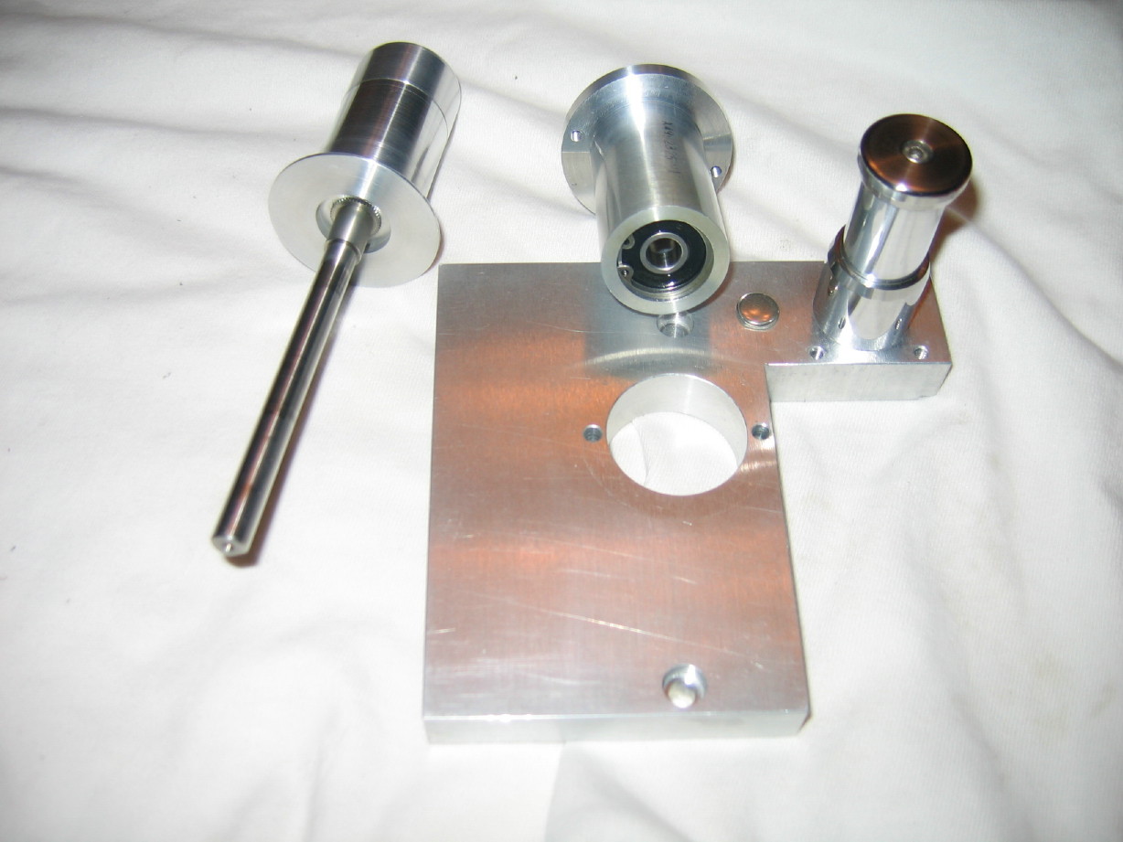
...okay, its late. I'm going to see if anybody at the Ampex List can help me on that one as well as what oil to use.

But nothing could have prepared me for what I saw when I opened that thing up...It was a combination of feeling like I should be wearing an isolation suit in a clean-room or that I had just discovered something from Hangar 18...look...at...this...thing...exposed innards of flywheel on left, coverplate on right:

IMG_6858_1_1.JPG


The inner flywheel is the silver part which rides on that big Fafnir bearing. The tolerances are so close...Its a really amazing thing. Here's a closer shot:

IMG_6861_3_1.JPG


I ooo'ed and ahhh'ed, took a couple pictures and closed that sucker back up!

I think its low on oil.

So the whole reel idler assembly isn't all back together yet, but good progress.

I also realized (after playing with the transport a bit more) that the noise I'm hearing that tips me off to the tape tension varying is mostly coming from one of the flutter idlers in the headblock. I think I'll need to be taking that to the jeweler...but it takes VERY LITTLE change in tension to make the sound change and so I'm not so concerned about it at this point. I'll get the flutter filters cleaned and lubed and get the pinch roller rebuilt, adjust the pinch roller tension and see where I'm at.

It was a good excercise messing with the flutter idlers...I understand now how to adjust them.

I think that's it for now...

Its late.
 
Almost forgot...

I ALSO disassembled the refurbished rotary guide I got off my 440-8. I had to disassemble it to take measurements in order to make a drawing to send to the machinist...it needs a spacer underneath it in order to be used as a rolling guide on the MM-1000. This guide will replace the first guide that is right outside the headcover on the supply side. Then THAT rolling guide will replace the static guide just ahead of the erase head.
 
Does all this labor make you wish you had a wax cylinder recorder instead?
:drunk:

In a word, no. :laughings::D

I also did some more calculations related to the whole reel height spacing.

Here's the thing: there are compound factors going on here between using standard reels and precision reels...yes there is an overall thickness issue (standard reel is about 1.194" thick, and the precision reel is about 1.210" thick) but the flanges are different thicknesses too...and how the flanges mount to the hub is different...

Shoot...

Can't find my notes...I'll post back on this but the flanges on a standard reel are 0.050" thick, and the hub on a standard reel is inside the flanges...like a sandwich the flanges are the bread and the hub is the stuff inside. So the inside surface of the lower flange is only 0.050" taller than the reel table surface (or in my case the reel spacer). With a precision hub the flanges mount on an inset, and the flanges are quite a bit thicker...the hub is actually what contacts the reel table (or spacer in my case), not the flange.

I'll find my notes...
 
Back
Top