Ampex AG-440B-8 Story...

As per the idler tensioner, yes it's spring loaded and it is as far clockwise in it's slot as it will go.

So I wonder if it just needs re-clocked…the whole assembly. I can’t recall if the assembly mounts to the transport plate with 3 or 4 screws. I think 3. So maybe it needs rotated 120 degrees clockwise…

Modifying the daughter board eq modules is easy it appears. Acccording to here: http://www.uneeda-audio.com/ampex/ag440_equalizer_pwa.pdf

The difference between -01 and -03 is two caps. Actually turns out I have a pair of -03's and the rest are -01's.

Yeah okay…I was recalling it was pretty straight-forward.

Record card daughterboards don't need to be modified?

Nope. Nothing changes with the logic, nothing changes with signal that needs amplified, what changes is the EQ curve necessary for best response. And that’s on the daughter board.

That extra power plug is not the AC to the control box. It's a bit smaller than that.

Okay. It’s like the same size then as the power input on the transport supply on my MM-1000. Well where does the cable originate?

I should be honest about my intentions with this machine. The plan is to simply get it rolling tape like it's capable of, and recording on every channel, and then sell it. I hate to give up on it, but I found a MM1100 for a good deal, so planning to spend my time more on that machine. Just want to get it as least running for the next person who uses it.

Well I’d do the same thing all day long, just make sure the MM-1100 has had the field service updates to address the known problems with that model. They are as reliable as an MM-1200 with the updates. But an MM-1000, 1100 or 1200 is a better machine than the AG-440-8. Your AG-440-8 looks to be in pretty good shape and mostly complete, totally complete functionally. I just see some cosmetics missing.
 
Back at this again. How in the heck do I get the cap off the reel idler assembly? It appears from the drawings that the screws mounting it are accessed from the top. But how?
 
Cap? What cap? Can you post a picture of you pointing to the cap you are talking about? I’m not aware of a cap. You remove the flywheel from below and the roller “lollipop” slides out from the top.
 
Cap, I shouldn't have used that word. I meant the whole idler roller, 'lollipop' as it were. Okay, so I have to remove the flywheel. Thanks so much.
 
Cap, I shouldn't have used that word. I meant the whole idler roller, 'lollipop' as it were. Okay, so I have to remove the flywheel. Thanks so much.
Oh okay. Yeah, IIRC the flywheel fastens to the roller “lollipop” shaft via two hex socket set screws (use an allen wrench) that are 90 degrees coincident to each other. Then the flywheel slides off and you can then just lift the roller out from the top.
 
So, these are the only screws I am able to find. 4 on the inside of the flywheel. But these don't sound like what you're talking about. Is this a job that necessarily requires removal of the control box?
 

Attachments

  • DSCN5901.jpg
    DSCN5901.jpg
    174 KB · Views: 2
Omg you took the cover off the viscous-damped flywheel. So there was no fluid inside I take it?

No you don’t disassemble the flywheel.

The two set screws are at the top of the flywheel.

Use an Allen wrench like I said in my last post. I think the set screws are hex socket type.
 
Okay, thanks. I got the flywheel off and indeed there were holes to reposition the idler roller and tensionor about 90 degrees clockwise for the middle roller modification. All assembled and back together and it's pulling tape nicely now, with the idler tensioner in the right position. Just need to invistigate the tape lifter weakness in ff/rw, and I can call the transport okay (for now)
 
There was a bit of fluid on the lid and a few drops came out, but not much. Still plenty of lube in it. What a beautiful piece of engineering.
 
There was a bit of fluid on the lid and a few drops came out, but not much. Still plenty of lube in it. What a beautiful piece of engineering.
It’s not lubricant. It’s Dow Corning 200 silicon fluid. It’s supposed to be full. The fluid provides a coupling between the shell and the inner flywheel.
 
In regard to the tape lifters, I measured the voltage across the solenoid coil while operating the machine. At first it seemed like I wasn't getting any voltage, but after I'd given up, I noticed it was slowly ramping up, over 15 minutes to get up to 18V and the tape lifters work fine after that. Cap in the control box?
 

Attachments

  • Screen Shot 2023-04-02 at 4.34.04 PM.png
    Screen Shot 2023-04-02 at 4.34.04 PM.png
    336 KB · Views: 0
I think it’s supposed to be 30V. But if your brakes and pinch roller solenoids are working fine, I wouldn’t suspect the power supply because they all reference the same supply. The voltage slowly ramping up could indicate a high resistance joint lowering in resistance as it heats up. So check the wiring and connections. Another thing to do maybe first, and I can’t remember how the lifter solenoid connects to the transport control box, but I think it’s two scissor-type connectors, is to disconnect the solenoid, and measure voltage across the leads from the transport control box. Report back on that. Also measure the resistance across the coil leads.
 
Thanks for the help again, Sweetbeats.

Sorry for the delay in getting back to this. I get to it when I can. Anyhow, with the coil leads disconnected, the voltage from the control box is 34V, steady, not ramping up. So, it's something with the Solenoid probably (but the DC is a little high from control box. Is this voltage used in the electronics too?, which are disconnected at the moment).
The Solenoid coil resistance is 14 ohms. The arrangement is two (20 or 22 awg gauge) wires that connect on one end to the solderless crimp connectors that connect to the control box leads, and on the other end directly to the solenoid wires. One of the coil wires at some point had pulled out just a bit, was disconnected from it's lead (but not at the coil), so I soldered it back on. Perhaps this joint is a problem, but the lazy tape lifters have been an issue way before I soldered that lead to the coil. The other side of the coil I can't get to without taking the solenoid out. But 14 ohms resistance seems to indicate it's connected to it's lead wire. I did measure the lead wire's resistance (that I could reach) from the coil to the crimp connector and got .4ohms.
 
The +34V is not that far off of the specified voltage…thats, like, 13% above what’s spec’ed. I wouldn’t think twice about that, particularly when the other solenoids are working fine. And no the transport power is not the same as the electronics power. The transport power supply is in the transport control box. The +39V audio power supplies are in the boxes at the bottom rear of the console. You won’t ever see transport power commingling with audio power.

The fact it is not ramping up with the solenoid disconnected does not necessarily mean the solenoid is the culprit, but that is a logical deduction. You can have a failing power supply produce full clean power unloaded, but as soon as a load is presented the voltage may drop significantly or might get really dirty. But looking at a few things related to the solenoid itself is a good place to start.

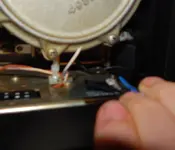
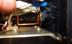
So there are non-factory wires and connections there, huh? That’s usually not great. 20~22AWG seems smaller than I remember so just look at that…don’t know if something got damaged at some point and wiring was replaced with “that’ll do” size. And solderless crimp connectors? Like butt connectors or quick disconnect bullet or spade type? Pictures would help.

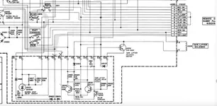
I don’t know what the coil resistance is supposed to be on that solenoid, but 14R doesn’t sound wrong. I was mainly interested if it was high resistance. It’s not. And if you’re measuring the resistance across the leads of the coil that takes into account the wiring. I still would be interested in a picture and your thoughts as to whether or not the wire size of the non-factory wiring matches up with the size of the wiring powering the other relays…the pinch roller solenoid and the brake solenoids. After that I’d visually inspect the wiring in the control box. IIRC there is a small PCB in the control box with the lifter return delay trimmer on it, some transistors, resistors, diodes, caps, etc. One side of the lifter solenoid coil goes to terminal E8 on that board so follow the wiring back to that and make sure it looks okay, if anything is suspect measure for resistance…and look at the board for any compromised solder joints or otherwise.

Now…here’s the other thing…have you done anything with the plug-in “ice cube” relays on this thing? It is super-common for contacts in these to oxidize, and/or wear past their service life. Almost always these are not sealed relays so they are open to the air (albeit with a plastic cover over them), so there is arcing and sparking and carbonizing and pitting, etc. Some people like me have thought “oh I’ll just open them up, clean and burnish the contacts and on my merry way I’ll go!” No. Best case scenario after “servicing” the relays: everything works relative to the relays for a little while but problems return. Typical scenario: some things improve for a short while, but not everything, and eventually things are back where they were. Sometimes scenario: old problems remain and new problems manifest. The easiest thing to do is just get new relays. If it’s a machine one is keeping it can make sense to get the hermetically sealed relays. They last longer. I think there are a total of 12 on an AG-440B-8…I might be wrong about that…4 on the transport control box, and 1 each on the back of the signal electronics modules (those are the record relays). These are 4PDT relays. I think the coil voltage is 24V. One set of the 4 contact sets in each of the REW and FFWD relays powers the lifter solenoid. You can bench test the relays…energize the coil with +24V to close the contacts and measure the resistance across the contacts 7 & 11…it should be a dead short.

The OTHER thing to check is to make sure the EDIT switch isn’t messed up. If there is a high resistance situation between the contacts when the switch is in the up position, the system could perceive the transport is sort of in EDIT mode, which includes a lifter cancel function. So you could temporarily bypass terminals A & C of the switch to rule that out. If you bypass those terminals (i.e. put a temporary jumper in place), and it works, the switch should be replaced.

Hopefully that gives you some things to work on. If it was my machine I would waste no time and at least replace the relays on the transport control box with new parts. Doing that alone *usually* addresses 95% of the problems one encounters with a an AG-440 machine.
 
Last edited:
Okay, I guess I'm going to have to take out the control box. Thanks so much for the leads.

Not such great pics, but the first one shows the crimp connectors on the right, poking out of the heat shrink. On the left the orange and violet/white wires go to the control box. In pic two, I'm trying to zoom in on the black wire connected to the coil. Anyway, these black wires are confirmed 20 awg, and the wires from the control box (orange and violet/white) look to be 22awg.

About what gauge do you remember? Tried to find reference in the manual . . . but no luck.
 

Attachments

  • DSCN5982.jpg
    DSCN5982.jpg
    176.1 KB · Views: 2
  • DSCN5984.jpg
    DSCN5984.jpg
    141.1 KB · Views: 2
Well, you can do that, or replace the relays. 9 times out of 10 you will be chasing your tail on transport stuff if the relays are an unknown quantity. I’d do that first.
 
Yeah, I did do that but using a spare relay of also unknown quality. Replaced them one by one with no change in symptoms. I can also test these on my 440b-2 track. I don't want to toast it's relays though by trying vica versa.

Do you have a source for new ones? I really need to get myself back on the Ampex list. For some reason my emails don't go through anymore.
 
Well if you changed relays and nothing changed, and come to think of it if the symptom is the same in REW and FFWD is *less* likely the relays are the cause or at least not the primary cause.

Take the button escutcheon off, jet some DeoxIT D5 down the collar of the EDIT switch and bap it with your finger 50 times. Also *verify* your remote jumper is correct and in good service. Wiring diagram is I. The AG-440B-8 supplement manual. The jumper straps the STOP, LIFTER CANCEL and ground together. They should be a dead short.

Disconnect the pinch roller solenoid leads. Measure the resistance across the coil. What is it? Is it similar to the 14R of the lifter solenoid coil? What happens if y or strap a 14R load across the leads for the lifter solenoid from the control box? Does it cause the voltage to ramp up slowly like when the lifter solenoid is connected? Use a larger resistor as close in value to 14R as you can find…maybe a 2W or 5W resistor to be safe. If the power pops up to something around +30V then I’d say your lifter solenoid is the problem.
 
Okay,
Reporting back with findings. I keep forgetting to squirt D5 in the edit switch but here are my findings otherwise.

With a 20 ohm resistor (no solenoid) connected to the tape lifter solenoid's power, I'm getting the same slow ramping up. No resistor, it's solid 34V. Resistor gets very hot too.

Also, I disconnected the pinch roller solenoid power, and am getting 1.5K ohm across it's coil. Very different. I then checked the power to the pinch roller (with the solenoid disconnected) and I was getting 139VDC. That can't be right. But I messed something up, and now instead of 139V, it's only putting out 1.5VDC and the pinch roller won't engage. The solenoid coil still measures 1.5K but I must have done something to the pinch roller power by inserting the 20 ohm resistor across it's power leads as well. Shouldn't have done that . . . or maybe I accidentally grounded power without noticing.
 
Well depending on the power rating of the resistor it certainly could and would get hot, and hot resistors are not uncommon. What did you use? 2W? 5W?

Because it did the ramp-up with the dummy load I suspect your power supply needs work. And the fact the no-load output is 1.5VDC affirms this. What happens if you switch to AC bolts and measure the output?

Bottom line I think your power supply is toast and it was already failed and now it’s really failed. Time to pull the transport control box, or actually I think you can just remove a cover at the front and get to pretty much everything.
 
Back
Top