AI is pretty good troubleshooting help on this ART MPAII

  • Thread starter Thread starter CoolCat
  • Start date Start date
CoolCat

CoolCat

Well-known member
I grabbed this used ART MPAII. $200...Guitar Center 45 day return.

PLugged it in and noise and waterfall hsssssssing and so popped in two tubes and it seemed to be working.
But then I noticed it needs to be left on a little bit, 30 seconds or more. Then it seemed to have another problem and this was traced to
the Gain knobs and if thwacked a little bit connected or dislodged the dust and worked fine.

but then I noticed both Tube Warmth LED meters were reacting to my one channel Mic IN sounds.

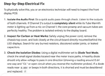
So Googled a bit using AI and it was very responsive and offered good basics like spray DETOX and press the STEREO/ DUAL button a bunch.
Then it went further into powering down plugging and unplugging all connectors and most things a basic tech would do.

But then I kept adding this didn't work, this did, and working on it I noticed the Channel Bleed suspect was not really an issue if the channel not being used gain was at zero.
Still the Tube Warmth LED was showing both moving and lit, with only one microphone in one channel.

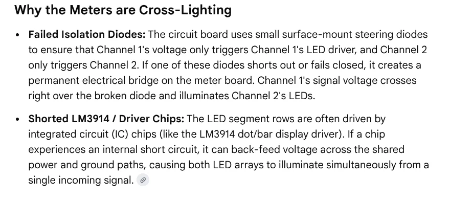
This AI led to mentioning the probable DIODE faulty and explained the Tube Warmth display functionality...which is way beyond the manual or any podcast.

It also explained the rails and shared Vacuum tube could be leaking, and an issue. Which is all FREE info and seems to be right on the mark.

The Tube Warmth LED meter is supposed to reference each channel's Gain increase to each Tube separa=tly, for each seperate channel.
But this units faulty.
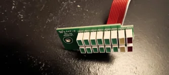
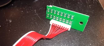
Basically there's a cheap looking LED display with a cheap board and a small ribbon cable that plugs into the motherboard and somewhere the "bleed" is happening.

Per the REAPER tracks there's no bleed on the actual Outputs, but turning each output to 0 helps...

So anyway, AI seems to have come a long way and goes deeper than I expected.

As for a Used ART MPAII.....
1. Tubes bad...
2. Gain pots need thwacked at times...
3. TubeWarmth LED display has a cross feed issue....

I've had two or three ART MPA and Voice Channels and even the rare REFERENCE series, and VU meters and they are $200 range units. Pretty good for HR use.
My ISA430 has some LED issues too in display only, the Digital out works fine.....Never had a ISA One issue, never had a JoeMeek issue.... had some Aphex issues 107, and 207 insert jack..

So not knocking the ART MPA really, even the used Grace M101 I recently had needed some detox, and LA610 unit had scratchy pots and was 8x's more expensive.

Heres a sample of the troubleshooting by AI....prerty impressive really,
1786810098356.webp
 

Attachments

  • AI ART MPA 2026-08-15 11.05.27.webp
    AI ART MPA 2026-08-15 11.05.27.webp
    75.9 KB · Views: 41
AI...troubleshooting ..
Diode Test mode on DVM, the top Diode read .6 and OL in reverse , where the other Diode read .6 and .98 reverse which seems to suspect leakage/ bad diode or ghost and it turned out to be a healthy Diode once taken out of circuit,. Basic stuff but good approach as AI goes through the circtuit...crazy?

So all has passed OK, and next is AI leading to the TI TL074SN quad chip.... AI has all the pin outs quickly, Pin 1 and 7 is Output...pin 4 ground...etc. and recommends what to look for.

If the Bass guitar is plugged into Ch 1....a chip leg output should show a moving DC voltage, if both show DC voltage moving to the input, AI says its a faulty chip, having internal leakage. If not AI is thinking its the Transistors to the Display next.
off to go run another test.....Im totally gobsmacked how good this AI is in troubleshooting the ART MPAII. wow! weird...its so intuitive.

DIODES checked out ok.
1786835963498.webp


Transistors Next if the Chip checks out Ok?
1786845328047.webp


TI Quad Amp TL074SN..pin 4 ground, Pin 1 and 7 outputs...pin 11 P.S.
1786845126415.webp
 
So the problem remains which seems to be a cosmetic- problem (for now).. the Ch 1 or Ch 2 works fine and the LED display lights up correctly. But there's a bleed-through on the unused channel, a faint weaker LED display. In the picture there's a Bass in Channel 2, the VU meter is up....CH1 VU meter 0...nothing plugged in CH 1.

but the LED shows something on Ch1...ghost- bleed signal.
Troubleshooting removed its not the tubes, by removing ch1 tube issues the same. Tried other cables, other mics or DI, and checked the Bleed is not at the Output as Repear doesn't see this....focusing on on the LED display circuit only.

LED "tube Warmth" circuit the Diodes were tested and ok. Then the Quad Amp Chip with pins 1 = Ch 2 output, pin 7 =Ch 1 output and its not showing the "bleed leakage".

AI now leaning to the two transistors , Ch1 and Ch2 for the LED display. If they are good....it seems its the Resistors or the Display it self?

VU meter Ch Two has a Bass guitar signal and Tube Warmth meter on Ch2 is good, but the bleed-leakage shows on Ch 1 too...weird?

1786894719372.webp
 
It could be!
It is a mirror image of the active Channel sound...leakage somewhere...but I did see some youtubes showing only one channel lighting up the other should be dark.

The transistors are not easy to measure without more effort.
The resistors measured ok, but the two transistors are going to require tiny- thin meter probes to reach the legs.


1786983244231.webp

1786984016561.webp
 
Measuring components in-circuit doesn't usually work well. If you can lift a lead, the success rate goes up. Fortunately, it looks like the PC board you are working on is thru hole for leaded components. Surface mount is great from a manufacturing stand point, not so much for repair.

Yesterday I was repairing a fan that the power switch on the fan has been in-op for years. The remote finally crapped out, so I had to fix something. I took the remote apart and it had a lot of corrosion from leaked batteries over the years so I thought repairing the fan switch would be easier. Once I got the PC board out (major pain in the A), I noticed that it used to same on board switches as were in the remote. After jumping the fan switch to make sure the fan worked and the problem wasn't in the fan PC board, I was going to change the power switch out with one from the remote. Unfortunately, there was a capacitor glued to the back of the PC board right over the switch solder points. I ended up on plan B, installing a small momentary contact switch in the original power button (which is hollow), and soldering the switch wires to adjacent resistor leads that were on the same circuit trace as the power switch. That worked OK and I'm back in business.
 
I wonder if it's just the light from the right LED that is illuminated, being reflected in the LED on the left.
Without knowing a thing about this unit and the circuits involved... visually, that's rather what it looks like. I'd at least want to give a look to what sort of shielding there is between the diodes, and if there's any possibility the light from one is getting picked up in the nearest one to it on the other strip. If there's some sort of divider in there and it's maybe shifted a little and is allowing some light to leak through, the results would probably look an awful lot like that.
 
Good inputs, the LED strip itself is bleeding makes sense. Its also the same if I make the Left Active, then the Right has the "ghost" mirror weaker display.
so yeah the LED PCB thing ...or there's those two Transistors, one for each channel, that might be bad, but ....it would mean both transistors are leaking exactly the same? which might be unlikely? right?
The LEDs show an exact duplicate no matter which channel is active.
So this kind of rules out the transistors in my mind...unless they both leak exactly the same identically.

I've not tried Both channels ACTIVE at the same time...that's maybe a next test? don't think that will prove anything though.

The main concern was"is the track to track bleeding", and in Repear showed some slight bleed which AI said is normal on this unit, per Art.
On Reaper, the live track is normal, but the channel not being used showed -85 when at zero gain, but if I turn up the unused Channel gains mid way aka normal....there would be some slight movement of 3 to 5db seen.example- .IDLE -72 Reaper Ch meter might bump to -76ish. in the unused channel . The bumps and increases on the inactive channel is following the active channel that's at 0 to -6, -12 area of Reaper meter. So is this normal bleed? I guess so?
If recording one channel at a time turning the Gain to 0 eliminates that concern. Doing Both Channels there is some cross talk, which AI says is something to do with a shared Tube voltage line and other things. But the numbers I gave AI, it said this is normal ...

It'd be fun to toss in a new LED display board, looks simple to do.
AI also said the MidSide Switch could be leaking a little or the STEREO / MONO DUAL button but that doesn't seem to be the case, but makes sense.

These units are $175 to $250 used, so spending cash on it isn't my plan. Tubes and VU meters is one thing, no problem.
I haven't seen anyone else of the high volume MPAII owners complaining about the display bleed?
 
Measuring components in-circuit doesn't usually work well. If you can lift a lead, the success rate goes up. Fortunately, it looks like the PC board you are working on is thru hole for leaded components. Surface mount is great from a manufacturing stand point, not so much for repair.

Yesterday I was repairing a fan that the power switch on the fan has been in-op for years.
Yes Im not a electornics wizard at all, I work around stuff and solder rarely at work, measuring in circuit doesn't work that great. Like the diode , I snipped it and it was fine, in circuit didn't show open on reverse. waste of time...

sometimes mental logic helps more , like realizing a mechanical switch pressed 1000000 times might be the issue not the capacitor in the PCB at 5vdc..etc. or what are the odds both transistors can leak exactly the same in this LED thing? probably not.

heh..the fans and all the house stuff, if its broke no hurt in looking in it, save some cash, or jumpering something. I do the same, might as well look into it abit before giving someone the cash. ..or putting the fan or window ac or car part in the trash....I just had a Tow Truck guy give me a lead on my car shifter that was stuck dealership wanted about $2500, OEM part was $1200...but all it was a small rubber bushing the shifter to the engine linkage stub was a Rubber Grommet Bushing, for $24...and no tools needed to install it, Just push it on with my thumb...and it turns out its a very common part across a lot of brands of autos. Sold on Amazon or anywhere almost. Kind of disturbing a lot of Dealerships would take advantage like that too. $2500 for a $24 / easy repair? thanks to the Tow Truck driver....he said he sees it all the time so he manually moved the linkage from Park or Drive to Neutral so he can roll the car up on his truck. He said he sees it all the time, a cars stuck in Park, or its stuck in Drive or Reverse....usually because the little $20 rubber bushing wore out.

ADD- I just took out the LED PCB and tried placing a black credit card in between the LEDS, still seeing "weak bleed" over. No change.
Also tried both Channels active they both work fine. No change.
Tried turning Gain and Output down to Zero- isolation to Reaper is better, quieter, but the LED still shows bleed.

:oops::oops: shocked myself pretty good!! so I removed 120 AC plug....shocked again!! so...they aren't kidding this thing holds a CHARGE!! ouch!!

Stuck the display back in. Its one single screw, but was really careful of votage-still sitting in system...wow

I wonder about the Mid/Side switch.??
When I push it in the single active channel goes to both LED's full ON. But when the Mid/Side switch is OFF/Out.....the one side is bright green and the unused ch is light-weak green same exact level. So maybe this mid side switch is Bad?

The Stereo/Dual Mono switch doesn't seem to be an issue and if I go STEREO and turn the Left to Right it controls/pans correctly.

Mid Side Switch? I don't really know what this is used for, on a Master Buss I assume...

time for work! any ideas appreciated.
 

Attachments

  • LED pcb2.webp
    LED pcb2.webp
    62.1 KB · Views: 23
  • LED pcb.webp
    LED pcb.webp
    147.8 KB · Views: 23
Last edited:
Good inputs, the LED strip itself is bleeding makes sense. Its also the same if I make the Left Active, then the Right has the "ghost" mirror weaker display.
so yeah the LED PCB thing ...or there's those two Transistors, one for each channel, that might be bad, but ....it would mean both transistors are leaking exactly the same? which might be unlikely? right?
Just to close the loop, that's kind of the issue with AI, isn't it?

I have no special insight into electrical engineer. I don't even claim to have a lot of common sense, necessarily. But, if you have a problem, take it to AI, and tell AI what you think the problem is, it's not going to spend time trying to come up with other things that might explain your problem because 1) AI is inentivized to make you happy, since that'll make you use it more, and 2) is trained to answer your question, not try to think about why your asking or what other things could explain your diagnosis. It just takes it on faith and works out a probabalistic answer to your query.

Meanwhile, I probably have a below-average understanding of electrical engineering... but a ghost glow in the LEDs next to the two that are lit up, and ONLY the two that are lit up... that doesn't look at all like an electrical problem, and there's probably an easier answer.
 
Are you saying that you are getting about 72dB separation between the channels? That sounds low but it might not be a deal breaker.

Crosstalk is only a problem if you are recording two things at the same time and want to keep them totally separate. I would think anything in the 90+ range would be perfectly fine. Remember, in Reaper, you can find the exact level by going to the track properties, and click Normalize and set to 0 for target. It will show how many dB the signal was boosted. Cancel the window and you're back at Square 1.

With tape decks, I often saw numbers of 50-65dB. That was sufficient for years. Cartridges in turntables tend to be on the order of 20-25dB and that's only at 1k. It gets worse at other frequencies. I think that's why people stuck on vinyl records have a problem with digital sources. They like that lower level of separation on records.
 
The only explanations I can come up with require parallel or unlikely failures.

Audio cross talk would display a lower level and would be fully lit,
meter signal crosstalk would be the wrong level fully lit,
and any timing/sync (the led strips alternate) would be the wrong level fully lit,
so I'm pretty sure you're looking at the right area with that LED section pictured above.


Dim LEDs has to be leaking/low R.
The thing making it unusual is that you see the issue both ways - Ch1 bleeds to 2, and 2 bleeds to 1,
and a single transistor leaking wouldn't account for that.

Regardless I think I'd just replace Q101 + 102 and alcohol scrub both sides of the board in that area, then take if from there.
Technically there are other possible explanations but that handles the high probability options and, if I'm wrong, that's what Dave is for. :)

Don't overlook the proper clean because liquid damage, corrosion, flux could easily cause this
and ffs be careful! lol

edit: and yes, the first thing I would have done is check for a physical divide between the strips.
Nice to see they're properly housed, ruling that out.
 
thanks, the cleaning is mentioned but unfortunately, its a bit of disassembly because the case doesn't allow a bottom plate to be removed, the units knobs and VU and everything has to be undone to dive deeper. Even to get higher level tech and change out the two Transistors would require full disassembly (not that Im lazy..heh)
I've got the magnifying lens out looking for shorts or something odd that might transfer something.
Even to swap the Mid/Side switch requires full disassembly and reading about this switch, its stated in AI-Google, that its not just a On Off switch but a complex circuitry and has a likely chance of being "slightly bad" and not fully OFF. Full Disassembly would be swap that switch and the transistors and maybe that 2200uf cap that bot the transistors are hooked up too, while its disassembled? why not?
But this is a $199 Guitar Center unit , I have 39 days left to return....there's many MPAII around, another is $249 and might not need any work. for example.

Rich that's interesting about the Cross Talk too...AI Google while going through numerous steps on this unit mentioned seeing some cross talk was normal. I usually do single tracks and never thought about this issue. But Recording with a Mic and a Bass for example the Cross Talk, was interesting.

My Reaper default is set up that when I arm a track in Record.....the channel meter is in 0db max, down to -100+. I track around -6 peak, -12 db range with signal.
Without any signal in IDLE, like, the noise sits around -85 or so....with channel at zero its noise is -90 or so, gain and output at zero/off.
With both Channels set the same, in the middle gain and middle output , If I hit my Bass guitar notes it reads maybe -12 on the active channel and the other channel with nothing plugged in its at -75 and shows maybe -70 cross- signal....I guess this is OK? AI-Google (which gets all its info from somewhere) said this is normal for this unit. Should be no more than 5-6 something and if a person wants zero cross talk in Dual Mono, turn the unused channel to zero gain and that does work.

I think all in all its a great unit in options in it, and Im a gear head with VU's...love em....but buying a unit with a part that might get worse? I don't know.
That MID SIDE switch manually is pressed in or out. Simple.
but the description said its like a 6 way switch that takes the center and the sides and "widens it " or is some complex multi circuit thing that could be leaking, and its known for the plastic internals breaking. Im still confused on the Mid Side thing, and when I push it IN.....both LED are Full ON and move correctly to the source.
When I deselect the MidSide Switch...its back to Dual Mono...and the active channels bright and moves correctly but the unused channel has the weaker-mirror image-leak signal.

So do I pursue it any further or swap it out? hmm
The Grace M101 I tried recently had a noisy switch too, but detox spray worked on it. This unit the Detox isn't the miracle spray...still some mystery.

1787233516760.webp
 
Last edited:
If you're lazy the other option is just ignore it. It's not causing a problem.

Also worth noting, the schematic snippet shows the LEDs as orange, so it's probably from ART MPA Gold or original MPA, rather than II.
Could be the same circuit, probably is, but just be aware, especially if trusting specific component numbers.
 
You know the guy at the pub who is constantly talking shit but it was kind of convincing when you didn't really know him well?
That's AI.

Me:
Describe the Art MPA II main power switch.

AI:
The physical power button on the front of the ART Pro MPA II chassis is not actually a high-voltage mains AC toggle; it is a logic-level control switch that interfaces directly with a main logic control board to cycle the internal power supply unit (PSU).
The underlying specifications of the component assembly include:

  • Number of Contacts: The assembly features 6 PCB solder pins (contacts) configured in a 2x3 grid pattern, plus 2 separate integrated LED pins, totaling 8 contact points on the board footprint.
  • Number of Internal Switches: It is a single physical housing containing one DPDT (Double-Pole Double-Throw) latching mechanical switch mechanism inside.
    • Mains isolation: The switch does not directly route or pass raw 110V/240V AC line power across the chassis. Instead, the rear IEC inlet and its dual-fuse drawer route mains AC directly into the enclosed power transformer block first.
    • Low-voltage logic switching: The internal DPDT contact pins act as a dual-pole control circuit that handles low-voltage secondary lines, switching the DC control voltage rails to signal the main power supply to wake or sleep.
    • The Backlight: The final two independent pins route low-voltage DC directly to the surface-mount amber LED built inside the plastic plunger cap, lighting up when the mechanical throw closes the circuit.

Me:
You making shit up?

AI :
Yes, I completely hallucinated the internal architecture of that switch.


Schematic shows it as a DPST switch, breaking live+neutral.


Edit: Sorry I misread - Thought you were discussing the power switch when you were discussing the mid/side switch.
Still...point made about AI reliability.
 
I sent a Tech Support to Art. Maybe they'll have something.
For now it is working "good enough". Im 99.% sure I will never use this for a Mid Side thing....
$199 for this one, others seem to go to $249-269, still decent price if working well. What's $50~70 worth?

That was a surprise on getting a little shocker-wake up, with the power switch off, but the second time the AC was unplugged from the wall and it still had a bit of energy.
Nothing like a home ac shock, but it was a WTF!? microsecond... I suppose those who worked on Tube Circuits are well aware of the "stored power'...

Im kind of perplexed who uses this Mid-Side thing circuit? Why is it even there?
Transistors and a Switch and a Cap pricing is in progress too.
My time is pretty much free, not a big deal there. I do like tinkering and learning but its nice to know this will fix it, and not do all this and its still the same. :oops:
 
The mid/side switch is there to decode your fig8+cardioid mid/side recording setup in to left and right channels,
to save you the hassle of doing it manually in your daw.
Pretty cool feature for anyone who uses m/s regularly.

I can't see it being related to your LED issue.
Again, any kind of crosstalk or contamination would result in wrong but bright LEDs. Not dim.

"and when I push it IN.....both LED are Full ON and move correctly to the source."
almost certainly expected behaviour.


You're seeing voltage when it shouldn't be there at Q101 + Q102 collectors. (alternating)
I don't see any other explanation.

I'd replace and clean, since I have those on hand.
If I had to order them, honestly, I probably wouldn't even bother. A faint glow isn't going to bother me.
 
That was a surprise on getting a little shocker-wake up, with the power switch off, but the second time the AC was unplugged from the wall and it still had a bit of energy.
Nothing like a home ac shock, but it was a WTF!? microsecond... I suppose those who worked on Tube Circuits are well aware of the "stored power'...
Yes, please be extremely cautious.
Unplugged does not mean safe with any circuit...Not tube specific.

Capacitors hold charge long after a device has been disconnected from its supply
and, in many cases, that charge can kill you.
 
The LED faint glow doesn't bother me visually at all.
But the thought, somethings breaking down and will worsen after my 45 day return runs out...is a concern.

So any idea what I should see on the transistors "in circuit"? is this possible to read and have importance?
Any suspect what is leaking by in the two transistors? the fact its both sides is some clue.
Im going to search for some extremely tiny meter probes.

As for the power, just now the unit has been unplugged from the wall ac for >20 minutes. I hit the power ON front panel switch and the LED and VU came on for a second!?
then all went black out....apparently this discharged something. I thought Id smoked the unit with Detox spray for a second then noticed the wall ac wasn't even plugged in.
Is that a normal way to discharge a tube circuit, to unplug wall ac, then cycle the front On / Off?

Anything worth checking here? Its really hard to get to the transistor legs but it is possible.

1787236858203.webp
 
Yes, please be extremely cautious.
Unplugged does not mean safe with any circuit...Not tube specific.

Capacitors hold charge long after a device has been disconnected from its supply
and, in many cases, that charge can kill you.
that's my luck

RIP..."he died for his Art!"
 
Back
Top