Tascam 388 power supply question

j.harv

@#$%
I have a Tascam 388 set up in my home studio. I came across a spare power supply card that I had laying around, so I decided to order all new caps for it to recap. Still waiting on the caps to arrive. I thought I'd recap this spare PSU being that it's already out of the machine and swap it in when refurbished. But.... I just pulled the power supply out of my 388 and it's configured differently than my spare.

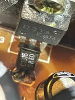
The spare, that I am going to recap, has a small black heat sink on the top corner with a transistor attached. The original PSU to the 388 im usung right now, doesn't have this. But it does have a couple resistors on the back that the spare doesn't have.

My question is can the spare PSU that I plan on recapping be used in place of the original PSU even though they look a bit different.??? Could it cause an issue?
I have included pictures. Spare PSU on the top, Original on the bottom in the first picture. Spare on the left in the second picture.
Cheers

006.JPG

007.JPG
 
Last edited:
Hey, @j.harv, the two versions should be pin-compatible…should be able to plug either one into the cardbay. What is the revision number of the PSU card assembly with the heat sink? Is it -01? Like Is the number printed on the board 52101739-01? I can’t tell from the pic. It is common for components and circuits to be updated during the life cycle of a device. That’s why you often see printed in a manual “specifications subject to change” or something like that. So somewhere there is another version of the manual than I have…mine has the -00 version supply in it. If I’m right and your spare is suffix -01, It is safe to assume the -01 assembly is improved over the -00 version. What’s improved? I don’t know since I don’t have the schematics. If it was me I’d rehab the -01 supply. And, again, it should plug right in as I doubt they would go to the expense of revising the motherboard with a different pin configuration.
 
Hey, @j.harv, the two versions should be pin-compatible…should be able to plug either one into the cardbay. What is the revision number of the PSU card assembly with the heat sink? Is it -01? Like Is the number printed on the board 52101739-01? I can’t tell from the pic. It is common for components and circuits to be updated during the life cycle of a device. That’s why you often see printed in a manual “specifications subject to change” or something like that. So somewhere there is another version of the manual than I have…mine has the -00 version supply in it. If I’m right and your spare is suffix -01, It is safe to assume the -01 assembly is improved over the -00 version. What’s improved? I don’t know since I don’t have the schematics. If it was me I’d rehab the -01 supply. And, again, it should plug right in as I doubt they would go to the expense of revising the motherboard with a different pin configuration.
Thanks Cory.
The # on this one is
52101739-02

But upon closer inspection, I just noticed the small transistor behind the heat sink looks to have some scorch marks around the base of it. And on the other side of the card where the solder joints are is showing the same.
I didn't order that part at all, although probably not hard to source. But, it could be an issue with something else in the original 388 for this card that has caused this.
I don't want to dive too deep into this. Just wanted to do a PSU recap. I could always just stick to refurbing the original card.
here are some pictures

002.JPG003.JPG
 
Oh wow -02…okay.

Yeah it’s not typical for a TO-92 cases transistor to get hot like that unless it was poor design, but I’m not guessing that’s the case here. What is the scorched part. Can you still read it on the face of it? And what is the part that’s mounted to the heat sink?

None of this stuff is on my schematic of course…I’d have to reverse engineer it from the actual assembly in absence of a related schematic.
 

Pretty bog standard NPN small signal transistor. Now Mr S knows this gear far better than I so I shall just say that if that board has been in operation for 20 years or so, that is not an unreasonable result? But then maybe I have seen to much whale **** domestic electronics!

Given the data up top it might be as well to measure the volts around it and see if it is being run close to its specs. The associated power transistor might have an unusually low hfe and thus demand more current from the wee device than it is perhaps happy with?

Certainly both components need to be replaced and the PCB cleaned before soldering. If the DC conditions show the transistor is being stressed too close for comfort maybe look for a 1W alternative or maybe a T05 device with a 'top hat' heat sink?

https://www.diodes.com/assets/Datasheets/ZTX692B.pdf ?

Dave.
 
The two versions are pin compatible. The two extra transistors were added to regulate the "NST" voltages.
Cool. Thanks for the info. Im gonna replace those transistors. Is it just the first numbers on the part that has to match?
The Transistor has C1815 GR6D on it. I looked up those parts but Im getting just the first part of the number C1815 with a different number on the end. Would this be compatible?
The suffix refers to different gain (hfe) groups. This is not usually critical in most circuits in fact in good designs, overall gain is set by resistor values and is largely independent of the parameters of devices.

Just an added thought. Don't go for 'crazy highest hfe' in the belief that "highest is best". That can lead to parasitic oscillation and thus noise on the supply lines. A good 'scope, 50mHz or better is really mandatory for this sort of work.

Dave.
 
Last edited:
The suffix refers to different gain (hfe) groups. This is not usually critical in most circuits in fact in good designs, overall gain is set by resistor values and is largely independent of the parameters of devices.

Just an added thought. Don't go for 'crazy highest hfe' in the belief that "highest is best". That can lead to parasitic oscillation and thus noise on the supply lines. A good 'scope, 50mHz or better is really mandatory for this sort of work.

Dave.
Could you recommend or point me in the direction of what transistors I need to replace those two?
I do have an electronics supply close by with racks of transistors, but I wouldn't know which ones to get.
It seems a little different than picking out capacitors, which are easier to identify for me personally.
@wkrbee Many thanks for confirming the two versions of the PSU assembly are pin compatible. I figured as much but having your verification is reassuring. And looking at the schematic for the -00 version and seeing no regulation on the NST rail, I wondered if that’s what the additional transistors were for. Thank you.

@j.harv So the -02 assembly really is the better assembly, and if it was me I’d be refurbishing the -02 assembly, putting it into service, and then shelving the original -00 assembly as a spare backup.

On your transistors the “C1815” is a 2SC1815. This is a current in-stock part and readily available…don’t know if that’s the case at your local shop or not but Mouser, Digikey etc. all carry the part. It’s a small value NPN general purpose transistor, and the style case yours is in is a TO-92, so you’re just looking for a TO-92 cased 2SC1815. Here’s a link to the part at Mouser and on the product page is also a link to the datasheet in case you want to take that to your local shop and ask for help finding a compatible part if they don’t have the exact part:

https://www.mouser.com/ProductDetai...C1815-GR-PBFREE?qs=IS%2B4QmGtzzrgrGkanbP22A==

For the other transistor, the power transistor, that’s a little more complicated because the D313 is not a current part. I’m sure you can find NOS stuff on eBay or whatever but likely it’s cheaper to get a current equivalent part, and this is not hard to find. The key specs you are looking for is a TO-220 cased 3A 60V NPN power transistor, and the other thing that’s not totally necessary but sure is helpful is to make sure it has the same pinout. The D313 is:

1. Base
2. Collector
3. Emitter

We also call this “BCE”. Here are three equivalent in-stock parts at Mouser with the correct pinout…should all be drop-in parts:

https://www.mouser.com/ProductDetail/STMicroelectronics/2ST31A?qs=CBOTe0%2BbgkaB4VvLhNvbfg==

https://www.mouser.com/ProductDetail/onsemi/TIP31AG?qs=xZq1yRCsb1dOxkCgH1ehng==

https://www.mouser.com/ProductDetail/Central-Semiconductor/TIP31A-PBFREE?qs=u16ybLDytRZhf95WGcl3sw==

The other thing I would do is, instead of just soldering the new parts in like the old ones where the pins are straight through the board and soldered to the pads, bare some of the copper traces leading from each pad of each transistor, tin the bared sections, and when you insert the transistor bend the pins so they are laying on the newly bared sections of traces to increase the contact area. This may help long term with heat related issues. Sometimes these joints that get hot will fatigue and then that increases resistance and then there’s more heat and we can ultimately see a total failure of the joint. It may not be a problem here, but I do see some discoloration from heat, which can be normal over the years, but if I see that I often do the above preventative measure.
 
@wkrbee Many thanks for confirming the two versions of the PSU assembly are pin compatible. I figured as much but having your verification is reassuring. And looking at the schematic for the -00 version and seeing no regulation on the NST rail, I wondered if that’s what the additional transistors were for. Thank you.

@j.harv So the -02 assembly really is the better assembly, and if it was me I’d be refurbishing the -02 assembly, putting it into service, and then shelving the original -00 assembly as a spare backup.

On your transistors the “C1815” is a 2SC1815. This is a current in-stock part and readily available…don’t know if that’s the case at your local shop or not but Mouser, Digikey etc. all carry the part. It’s a small value NPN general purpose transistor, and the style case yours is in is a TO-92, so you’re just looking for a TO-92 cased 2SC1815. Here’s a link to the part at Mouser and on the product page is also a link to the datasheet in case you want to take that to your local shop and ask for help finding a compatible part if they don’t have the exact part:

https://www.mouser.com/ProductDetail/Central-Semiconductor/2SC1815-GR-PBFREE?qs=IS%2B4QmGtzzrgrGkanbP22A==

For the other transistor, the power transistor, that’s a little more complicated because the D313 is not a current part. I’m sure you can find NOS stuff on eBay or whatever but likely it’s cheaper to get a current equivalent part, and this is not hard to find. The key specs you are looking for is a TO-220 cased 3A 60V NPN power transistor, and the other thing that’s not totally necessary but sure is helpful is to make sure it has the same pinout. The D313 is:

1. Base
2. Collector
3. Emitter

We also call this “BCE”. Here are three equivalent in-stock parts at Mouser with the correct pinout…should all be drop-in parts:

https://www.mouser.com/ProductDetail/STMicroelectronics/2ST31A?qs=CBOTe0%2BbgkaB4VvLhNvbfg==

https://www.mouser.com/ProductDetail/onsemi/TIP31AG?qs=xZq1yRCsb1dOxkCgH1ehng==

https://www.mouser.com/ProductDetail/Central-Semiconductor/TIP31A-PBFREE?qs=u16ybLDytRZhf95WGcl3sw==

The other thing I would do is, instead of just soldering the new parts in like the old ones where the pins are straight through the board and soldered to the pads, bare some of the copper traces leading from each pad of each transistor, tin the bared sections, and when you insert the transistor bend the pins so they I
Awesome. Thanks again Sweetbeats!
I'll have a sniff around the store to see if I can pick out the parts. If not, I'll have to order from Mouser again. And thanks for the soldering tip too.
 
@sweetbeats Do you think these would do, they are in stock

This power transistor is rated at 80v, would that be ok?

As for the other transistor, Im not sure what Im looking at when I browse this page. Is there anything on here that would be the compatible?
 
The TIP31B should work fine. Like I said, you’re looking for a transistor that’s TO-220 cased, and rated for at least 60V and 3A. The TIP31B meets that criteria. The last piece is the pinout. I did you the liberty of finding the datasheet and looking at the pinout. You can do the same thing. Search for “[name of part] datasheet”. Then remember for a transistor like this there is the base, the collector and the emitter. Those are the three pins. The datasheet shows you the pin orientation which, to match the D313 needs to be pins 1 through 3 from left to right as you look at the face of the transistor. And then the pin assignment needs to be B, C, E for pins 1, 2, 3 respectively. There are ways to install replacement transistors with different pinouts, but it gets a little more difficult to eloquently accomplish with a TO-220 part as compared to something like a TO-92 part. Anyway, the TIP31B has the same pinout.

Now for the 2SC1815 replacement, the problem is your vendor doesn’t have any way on their website to filter or drill down to the specifics of what you need. They make you either know the part and know exactly what you’re looking for, or make you search on your own for the datasheet and then hunt for the specs on the sheet to see if it’s a match. You can visually filter out the stuff that’s not TO-92 cased. You don’t need to stuff something that’s in a different case like a metal can for instance into the spot where the 2SC1815 is mounted. You pay more for the metal cans and the bigger parts probably have a higher rating than you need, so that’s a waste of money. I don’t have time at the moment to go researching maybe dozens of parts, especially when you can get the exact replacement part from Mouser without any wonder.

If I get a chance here shortly I’ll look at the first couple parts to see if there’s a good enough match but I just can’t commit to more time than that on this. No offense.
 
The MPSA05/06 would probably work, but they have the wrong pinout. You are looking for ECB and the MPS parts are EBC. Again you can install them but you have to be careful and make sure the base and collector pins are appropriately reversed and then it’s a good idea to put Teflon tubing on at least one of those who legs to prevent shorting.
 
The TIP31B should work fine. Like I said, you’re looking for a transistor that’s TO-220 cased, and rated for at least 60V and 3A. The TIP31B meets that criteria. The last piece is the pinout. I did you the liberty of finding the datasheet and looking at the pinout. You can do the same thing. Search for “[name of part] datasheet”. Then remember for a transistor like this there is the base, the collector and the emitter. Those are the three pins. The datasheet shows you the pin orientation which, to match the D313 needs to be pins 1 through 3 from left to right as you look at the face of the transistor. And then the pin assignment needs to be B, C, E for pins 1, 2, 3 respectively. There are ways to install replacement transistors with different pinouts, but it gets a little more difficult to eloquently accomplish with a TO-220 part as compared to something like a TO-92 part. Anyway, the TIP31B has the same pinout.

Now for the 2SC1815 replacement, the problem is your vendor doesn’t have any way on their website to filter or drill down to the specifics of what you need. They make you either know the part and know exactly what you’re looking for, or make you search on your own for the datasheet and then hunt for the specs on the sheet to see if it’s a match. You can visually filter out the stuff that’s not TO-92 cased. You don’t need to stuff something that’s in a different case like a metal can for instance into the spot where the 2SC1815 is mounted. You pay more for the metal cans and the bigger parts probably have a higher rating than you need, so that’s a waste of money. I don’t have time at the moment to go researching maybe dozens of parts, especially when you can get the exact replacement part from Mouser without any wonder.

If I get a chance here shortly I’ll look at the first couple parts to see if there’s a good enough match but I just can’t commit to more time than that on this. No offense.
Thanks again. No need to search. and no offence taken. You have given enough of your time. Appreciated.
I'll most likely order the one part from mouser.
 
Yeah, I don’t mean to be a grouch…I totally know how it is, like, you’re looking at ordering two parts costing less than $2 and paying $8 shipping…your local shop does have some good prices, it’s just that as far as transistors it looks more like you buy from them if they have the exact part you need and are looking for vs hunting for substitutions. Anyway, do what you gotta do but if it was me I’d be stoked to put the correct part in if I could get it…but I’m a bit obsessive that way.
 
Thanks again. No need to search. and no offence taken. You have given enough of your time. Appreciated.
I'll most likely order the one part from mouser.
Looks like you have it covered friend with the kind assistance of Sweetbeats. Just a note of caution? I noticed one of the T092 devices you linked to was a Darlington transistor, avoid as the very high hfe (current gain) could again result in parasitic oscillation.

Also, I cannot see the heat sink for the power device or how it is mounted but you will need a 'mounting kit' insulating washer and 'top hat' bolt insulator and some heatsink compound, Make sure both the sink surface and the transistor are 'surgically' clean before mounting and then check with a meter* that the tab of the transistor is indeed insulated from the metal sink. Some designs 'float' the heatsink and mount the transistor directly to it so you would not need a washer in that case. Still need it clean and with the white gunk though.

*In fact ALWAYS worth checking each device pin to 'ground' i.e. zero volts with an Ohm meter with one eye on the schematic to ensure you have not put a 'blob' somewhere and thus a short. Takes but a minute. Can save hours. (not to mention hair and a swelling in the cussing tin)

Dave.
 
Back
Top