Tascam BR-20T Story...

Huh!

No it was just sitting on the dining room table connected to nuttin'.

Can you clarify what you mean by "go hot"? Like what kind of voltage are you getting and what are you measuring between?

I smell a grounding mod in the wind.

The BR-20 series do not have a grounding lug on them. Its acceptable for a device to get its chassis grounding through the audio connections but it's a dangerous assumption because then the assumption is that the device to which the deck is connected is properly grounding, and then it of course requires that the shield isn't lifted at either end and if there are pin 1 problems you'll have noise issues if one end was lifted to share noise.

I'll have to study how the pin 1 connections were handled on the BR-20 and address that, and then I'll likely incorporate a ground lug, and THEN I need to figure out what the purpose of the ground tab on the Noise Filter PCB is for, and if it is to provide a virtual earth for the chassis then it needs to be removed.
 
I was getting half-mains on two of my units, I believe I was measuring with respect to the earth pin on a mains socket. It was about the same as you - I brushed the edge of the chassis with my hand and it tingled. I thought it was static at first, but when it happened again I got out the meter.
 
Okay. Thanks.

I looked at the schematic for the TSR-8 mains input section and sure enough there is a noise filter PCB almost identical.

I bet if you check the voltage of the chassis to the building ground at the outlet you'll have around 120vac and then if you check current I bet you'll see around 40~60mA. There are caps on that Noise Filter PCB that will leak some current, and then there is one across the power switch which I believe is for arresting sparking. It'll leak too and when the power switch is open the voltage can only go across that cap, but when the switch is closed you create a parallel path and the voltage divides which is why you see about half-mains when the unit is on.

So I did some testing...

Ran a cable from the chassis to the building ground and the current stays the same but the voltage drops to about 50mV from around 60vac with the deck powered on. This means the ground wire essentially kills the stray current potential present on the chassis, which is what you would expect. The TRICK is to see if adding the path to the building ground causes a problem in the audio path.

I checked for added noise to the audio path and there is no difference either through the line jacks or the headphone amp. The headphone amp is horrifically noisy with thermal noise and motor noises all on its own which has been my experience with Teac h/p amps anyway, but the line out jacks are nice and quiet, same with and without the safety ground strap. So that means that with what I know at this point there is no harm in changing out the factory two-wire power cable for a three-wire cable and strapping the ground conductor to the chassis.

Out of curiosity I pulled the rear jack panel apart and looked at how Teac handled the pin 1 grounding and as I expected it goes diving into the
depths of the machine instead of tying to the backplane as close as possible to each respective jack. Not knowing how well or even how the rest of the system is strapped to the chassis I'm leaving that alone until RF interference presents itself as a problem if it ever does. The logic here is that you can't just go and tie your audio jack shields/pin 1 conductors to the chassis as close as possible to the each jack if they aren't already so, even though that is the best practice. It depends on how the rest of the system references the chassis. You could mess something up by not looking at the big picture; by not looking at how the whole ground scheme was designed. I learned this in a very big way when I reworked the whole ground scheme on my Soundtracs 32 x 8 console. So I'm leaving this alone unless I'm having trouble with the Hispanic radio station down the street infiltrating my masters. Then I'll have to study the schematics and work up the solution.

So I'll change out the power cable tonight and then with the tensions done and the grounding problem resolved I can get all the skin back on the machine and mount it back up in the rack (finally), check the azimuth and then proceed with the electronic alignment.
 
Been a loooong while since updating this thread and a lot has happened...

I did get the 3-wire power cable installed and reconfigured the pin1 grounding for the I/O jacks but in the process the headphone amp tanked along with the 15V audio rails. Kind of sad/frustrating to have a VGC machine that was fully functional sort of tank in a couple areas. And then in the process of upgrading/rebuilding the headphone amp I installed the wrong power transistors (wrong pinout and wrong voltage spec). I bought transistors on advisement from a friend. Its not his fault. I'm responsible for what goes into my machine. So that has complicated things. Anyway, just about got it back to where I was which is that I'm still having dc transport noise getting into the audio path and some wierd "grumbling" in the left channel. We're getting things narrowed down to the trouble source. We'll get it, and in the end the PSU has been rebuilt, the chassis is properly grounded, it'll have a rebuilt and upgraded headphone amp installed...just anxious to not have it's guts spilled all over the floor.

So here comes about 3 months worth of pictures on this project. I'll just put the pics up and put a caption with each.

Here is the noise filter PCB with the new 3-wire power cord installed. The light blue caps will be replaced on the PCB...those are the caps that shunt noise to ground.

IMG_3210_3_1.JPG


This is where the power cord enters the chassis and I'm fastening the ground wire to the chassis at one of the noise filter PCB lugs:

IMG_3212_4_1.JPG


And here's the noise filter PCB mounted up...the ground tab of the PCB has the ground wire of the power cord mounted right on the other side. I was even able to find hardware out of my baggie of screws and stuff that came off another Tascam machine.

IMG_3213_5_1.JPG


Here is the jack/balance amp PCB. I'm holding the original ground wire which connected to the board via a plug and then went into the machine. I removed the connector from the PCB and soldered on a wire with a ring terminal to bolt to the chassis as close as possible to the jack PCB.

IMG_3204_1_1.JPG


IMG_3218_7_1.JPG


And I almost forgot about this...I had to repair head cabling because one of the sync head cables had been pinched in the dress panel mount. You can see the pinched spot just below the zip tie close to the heads:

IMG_3219_8_1.JPG


To be continued...
 
Another thing I found that needed fixed was some flakey looking solder joints with some wires on the VR PCB which handles, in part, the input and output level pots. You can see the 3-conductor red/white/blue wire there in the foreground and it is hanging on by far less stranding than should be. I trimmed the whole thing off, cleaned the solder lands up, restripped all conductors and burned it in.

IMG_3231_1_1.JPG


Here is where we start getting into the headphone amp which shares a PCB with the meter amp circuitry. Look there in between the meters...you can see the opamp driver for the headphones and a set of 4 follower transistors. Yes...everything is all black lookin'. Them transistors get hot. Because of the amount of thermal noise in the headphones and everything looking all cooked it was decided to replace those transistors with new parts as well as resistors in the follower circuit, and I decided to recap the board and we adjusted the opamp feedback loop RC network by a factor of 10 (10x bigger capacitors and comensurate change in the resistors). I had to get a little creative with the bigger caps since its tight in there but it all fit. And I put a dip-8 socket in there for the opamp and changed the stock 4570 chip for a 5532. Anyway, here are "before" pictures, front and back. You can see how much the heat even soaked through to the backside of the PCB and yes the lands for the transistors were damaged (lifting from the board).

IMG_3233_2_1.JPG


IMG_3235_3_1.JPG
 
Here's the rebuilt headphone amp section with the *wrong* transistors. Oy. Transistors and what they do and how they do it has been a foggy area for me...and also how to understand their specs and such. This headphone amp debacle has been a great education.

DSC_0160_2_1_2_1_1.JPG


DSC_0161_3_1_3_1_1.JPG


Here's the solder side...Definitely not my proudest work...and you can imagine my thoughts as the new (wrong) transistors blew since there wasn't anything left to weld to when I put them in...like a plastic surgery gone bad...

DSC_0166_7_1_7_1_1.JPG
 
Sooooo....

Last chapter in this current installment.

Here is the headphone amp with the new new (proper) transistors. Double-triple-quadruple checked orientation and specification of these puppies. Yes they are a snug fit, and yes heating the lands up again to get the new/wrong transistors out put the final nail in the coffin on those lands so I basically had to make a medusa's mess of the tails on the parts to create pseudo point-to-point wiring between the transistors and the components on the board to which they interface since I couldn't trust the traces anymore. It looks better now that they're welded and trimmed, but it looked sick before that.

IMG_3267_2_1.JPG


IMG_3265_1_1.JPG


I haven't reinstalled it yet but that's next. Little nervous. Surprised?

I've been running some tests though and the good news is that the transport is functioning just fine and the switching logic and all that, so its back to figuring out where the hum and grumble is coming from on the left channel and the hiss in both channels. Its not the amp cards or the I/O jack board/balance amp. It is something in between which leaves wiring, motherboard or VR PCB. The problem only manifests in sync or repro. So there are enough clues to help narrow down the culprit.

Here is how the poor BR looked a few days ago when I was testing the rebuilt PSU:

IMG_3255_1_1.JPG


Stay tuned...
 
Epic Fail...

Installed the headphone amp...its dead, and it took out the power rails.

*sigh*

This is discouraging.

Need to get the BR-20T fixed to get to the MM-1000 to get to having a functioning studio.
 
Oh my...I was going to get this thread caught up...didn't realize the last substantive information was posted well over a year ago.. :o

This will take a little time.
Bottom line is that I ultimately handed it off to Ethan and he got it figured out in a jiff.

More later.
 
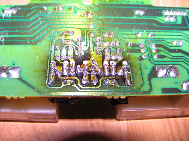
So we left off with a grumbly/noisy left channel in sync and repro mode and high noise floor/hum across both channels IIRC...PLUS the headphone amp wasn't working...this was after the headphone amp was rebuilt because the output transistors looked to have spent a long time at high temps...recapped it, replaced the transistors and associated resistors, did some trace repair on the board and socketed and upgraded the opamp...the transistors that were recommended and which I got were the wrong pinout and killed the headphone amp power rail upon installation. This was clearly my error...a rookie mistake. Recapped the entire power supply, still no-go, sent headphone amp to friend to verify operation and it was A-OK so something wrong with PSU, plus all the audio noise problems still existed. Frustrated, the BR-20T sat for months and months and months.

Finally decided I needed to do *something* so I tracked Ethan down and we decided it would be easiest for me to just leave the machine with him...Ethan being a super-busy fella, and me having no active need for the machine, it rested at Ethan's place for awhile, but I wanted to report an abridged version here what Ethan found and did for the sake of the "Story":

"The [headphone amp] fix: the headphone amp [gpower supply] was blown open [i.e. the current limiting resistors in the power supply had failed open...presumably when I installed the amp board with the incorrect transistors which likely caused the PSU to go WOT...that's Wide Open Throttle for you non-motorcyclists. :) This makes perfect sense. I was confused in that I was measuring correct voltage from the PSU with the amp board disconnected, but when connected the voltages would quickly be pulled to 0V...and it changed over time, got worse...so I'm thinking the resistors were toast and power had found some high-resistance path either through the "open" resistors or by some other means, but regardless was "toast".]

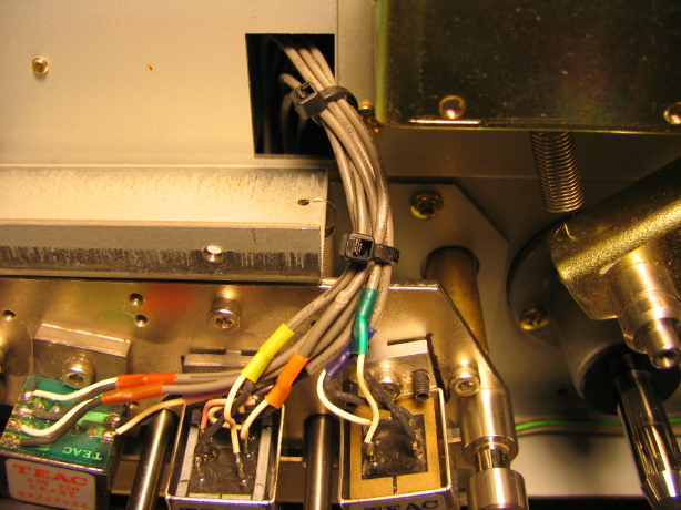
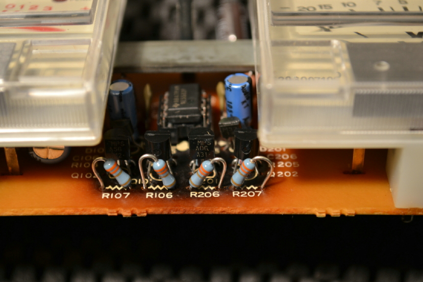
As for the noise: I chased signals around for a while and like you noted that it did not follow the rec/play amp boards when swapped. I did change the ch1/ch2 head wiring and the noise stayed with channel 1. This eliminated the head as a problem. Then I pulled the sync connection from the motherboard which allowed ch1 to be quiet for a few seconds then the buzz came back. Also I had shorted the ch1 sync inputs which silenced the noise (shorted input should be quiet).

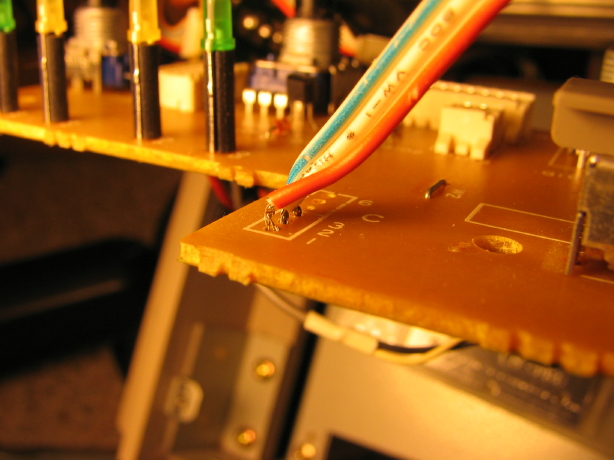
This really left the motherboard as the single thing common. I was loath to remove the motherboard and did touch up the connectors with a little solder just in case there was a crack. No change. Then looking over the manual I see that the sync head outputs go to the time code board. So I start tracing those wires.

Remember how with the head disconnected the output was quiet for a little while? Something like that takes a cap to charge up to get the time constant. Having the sync heads go to the time code board might give such a cap. And one channel could be bad and the other fine with something like this...when looking at the machine something was not right so off again to the manual and 
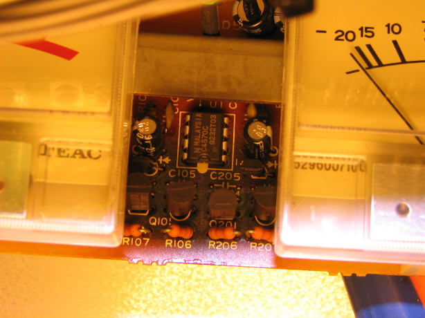
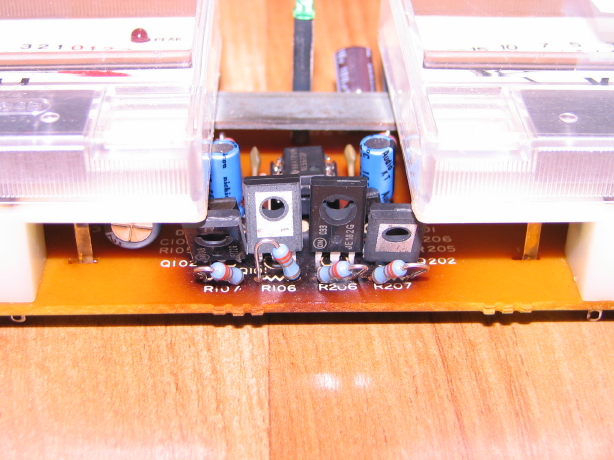
I discovered that the time code and bias/amp board were swapped. [yours truly is STILL slapping forehead and shaking head...] They were in each other's slots. Lucky that Tascam made it so they would not fry in this case but sad that they made it so that it was possible.

Putting both boards in their respective slots and the noise is gone, The deck records and does not have the distortion caused by the lack of bias...good news."

Indeed.

So me swapping the boards goes back quite a ways because I sequentially removed those boards as a troubleshooting step AFTER the problem was evident, meaning I must have swapped them during the cleaning stage. But I KNOW I was careful upon reinstallation. I betcha when I have the machine back in my possession it'll be evident what I did...I have a hunch I was referencing something upside-down. At any rate, it IS surprising that the cards would be able to fit in each other's slots...and VERY fortunate something else didn't fry, at least nothing that's known yet. :eek: But Ethan has done a basic play calibration and so far it is doing well.

Ethan was kind enough to send additional detail of his troubleshooting path relative to the schematics which is handy as a case-study then for future repair needs I may encounter.

Thank you, Ethan!

Should be able to go pick the BR-20T up in a week or so, give or take.
 
Back
Top