The Fun Never Ends With My 388 Misadventures

Mark7

Well-known member
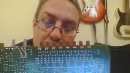
See the white plastic surrounds on the LEDs? The five on the right are all broken so the LEDs don't sit true. How easy would it be to replace them?2021-08-25-212337.jpg
 
Don’t replace them. The LEDs are probably fine, it’s just the white holder. The little clips that wrap around the top of the card are busted, yes? I run across that a lot on this vintage of Teac/Tascam gear and what I do is try lifting the holder away from the card a little and running a small bead of superglue under the holder, and then press and hold that in the position it would be in if the little clips were intact. Done. And then re-flow the solder joints between the card and the holder. Make sense?
 
Yeah, I figured it was the holders that were the problem after I posted. Thanks :)
Yeah they used these same kind of connector housings for card edge connectors, like multi pin type on the 58 and MS16 tape machine record/play amp cards…I don’t remember how many pins but there are two connectors per card and maybe 10-12 pins per connectors…2 little clips per connector…*schnap*…come to think of it it’s the same thing on the 388 plug in cards right? So that solution with the superglue works for those too if you run into that on any of your plug-in cards…lift, glue, line it up, press and hold into place, reflow solder joints, good to go.
 
I really really don't want to try soldering. I think I'll leave that to someone competent.

I've never seen a 388 plug in card.
 
The plug in cards include:

record/play amp PCB x4
Dbx amp PCB x2
Balance amp PCB x1
Meter amp PCB x1
Bias amp PCB x2
Reel servo PCB x1
Power supply PCB x1

they are all loaded in the card bay behind the meter bridge. Remove the screws on the top cover behind the meter bridge, lift the cover off and you’ll see them.
 
If I wanted to buy a new set of LEDs mounted in those white plastic holders what's the part number?
 
I put the thing back together to test it.

Plugged mic into channel 1 XLR
Put input selector in Mic position
Turned pre amp up to 3 O'clock
Set track 1/2 Assign button to on
Turned channel 1 pan control fully left
Raised channel 1 fader to unity
Armed track 1
Raised left buss fader to unity
Raised stereo master fader to unity
Plugged in headphones
Set monitor selector switch to Stereo and turned up headphone volume

The result was a horribly tinny sound and all 8 channel meter needles bouncing around. Any ideas what I did wrong?
 
That rats nest of connectors between the A, B and Monitor buss boards is really confusing. Does anyone have a clearly illustrated diagram of what goes where? Though I suspect it's not the cables and my 388 may be no longer capable of functioning. :(
 
The schematic in the service manual has all the connectors labeled to match the physical assembly, it even lists the color of the connector, and you can count the pins on the schematic. Just take one at a time.
 
Like specifically look at pages 4-3, 4-5 and 4-6 of the service manual. Those are the schematics for the Monitor, Buss A and Buss B PCB assemblies respectively. On each diagram along the left and right sides of the diagrams are all the connectors associated with each PCB and you’ll see the number of each connector and socket (like J104 and P104 for instance) and it’ll show the color of the connector and there’s usually a note for where each one goes.
 
I'm getting a good strong signal to the stereo buss and phones out jacks. The program busses are still not behaving as expected though. I looked at the diagrams and did my best (I'm circuit board illiterate) but there are way too many sockets that have the same number of holes and wires that can go to any number of plugs with the same number of pins that it's kind of a crapshoot whether or not I'll attach the right one to the right one
 
So... I somehow managed to get the stereo signal path working. The signal from the mixer channel (presumably all the mixer channels) now successfully travels from the mic/line input to the headphone outs (and presumably the stereo outs, though I haven't tried them yet). For some reason though I can't route the signal to any of the individual program busses/tracks. The signal I can hear is quiet and tinny and seems to be getting routed to all pgm busses at once. Is this a wiring problem or is there something wrong with my Monitor PCB? I'm guessing all the wires are coloured coded (brown is earth/ground right?) but the actual colours aren't listed in the 388's manual so I can't tell which set of wires is most likely the right one for any given plug/socket combo. Photos of the insides of the machine don't help much since it's such a spaghetti junction in there.

Does anyone have a guide to Tascam wiring colour codes?
 
Okay. Let's go back to basics. I've successfully hooked up the stereo buss. What connections did I make to do that? What connections do I need to make to send signals from the mixer channels to the pgm busses/tracks and then on to the monitor section? Forget the aux or effects busses for now.
 
On to the A board now. There are a group of wires soldered directly to the board that terminates in a red plug with 8 holes. There are two places it can connect to, One on the B board and one on the monitor board. Which one is it?
 
With all connectors, except the 8 pin red, on the monitor pcb connected the record arm indicators are now flashing but still no sound.
 
On to the A board now. There are a group of wires soldered directly to the board that terminates in a red plug with 8 holes. There are two places it can connect to, One on the B board and one on the monitor board. Which one is it?
That goes to P103 on the BUSS B PCB. See pic excerpt from the BUSS A PCB schematic:

D527DE7B-46A0-483B-987B-6718BFE6ED49.png
 
Okay. There's a loose cable with red and white 8 hole connectors at either end. Would it be right to assume that the white end plugs into the A board on the second set of pins down?
 
We’re not going to assume anything.

That’s what got you into this mess.

For people reading now and in the future, this is why you carefully label connections and take gobs of pictures before you tear something apart, even capture video. You can’t just plug stuff in willy-nilly and hope or expect it to work. Worst case scenario you do that and power it up permanently damage the unit. I’m not being dramatic. And I’m not saying that’s exactly what’s going on here, but in my opinion there seems to be a pattern of diving in with some level of reckless abandon and then getting lost and stumbling around trying stuff before asking for help, and then maybe or maybe not accepting the help and stumbling around some more. I can read you are now taking things kind of one step at a time and that’s good. You can even permanently damage your unit by powering it up with stuff disconnected. This is very true of the 388 with how it is designed.

According to the schematic there appears to be an 8-conductor cable with white and red connectors, the white end goes to P104 on the BUSS A PCB and the red end goes to P12 on the MONITOR PCB. I don’t know if this is this one you are asking about, I’m just regurgitating what’s on the schematic. Your descriptor “second set of pins down” means nothing to me. The PCBs and connectors are physically labeled. Please use the descriptors screened on the PCBs.

I don’t mean to be harsh. It’s just I often want to help you with these recurring situations, but I want you to learn to help yourself too by preparing and thinking ahead before you dive, in, and slowing down when troubleshooting needs to happen, especially when somebody is trying to help you. And I don’t feel like you do these things even when advised to do so and it’s frustrating…you end up killing your gear. So that’s where I’m coming from.

D776544C-0C12-48C4-83DA-E3AF9B397B95.png
 
Last edited:
Back
Top