Teac A-2300S no sound

Joe_Southern

New member
I have a Teac A-2300S (very similar to 3300). I fixed the common pinch roller problem (which I've done on other Teac's twice before) and after reassembly there isn't any sound. Transport works fine though :-)

The switch 'is' on Tape (not monitor), and there is no VU meter activity (except the lights do come on). Used a known good tape. No output using headphones or line out. Also, microphone input shows no activity either.

There isn't really anything I knocked loose that I can see. As I said, I've done this before and it's been fine.

So, no VU activity or output either through line out or microphones using either a tape or external input.

I'd appreciate any thoughts.
 
For the benefit of those that aren’t familiar with your machine, what is “the common pinch roller problem” and how is it resolved? What’s the procedure you had to execute to mitigate the common pinch roller problem? Knowing this will help fill in the blanks in your post about what all you worked on, what was disassembled, basically where you were messing around in the machine. Looking at the service manual, if the procedure to address the common pinch roller problem involves working on the pinch roller assembly from the back inside the machine, I see the power supply PCB is mounted toward the rear but in the same area as the pinch roller mechanism, capstan flywheel, etc. is it safe to assume the machine was unpowered and unplugged from the wall while you did all the work?

I’m not sure my set of schematics are complete, but it looks like there is no fuse block on the secondary side of the main transformer. I would normally check there if you have a sudden global loss of power or function across an entire device…but I don’t see individual fuses for the different power rails. So maybe look closely to see if you damaged the power supply PCB, even a hairline crack is all that’s needed to lose connection. Or old solder joints on brittle phenolic resin boards, and wires getting pushed around can compromise solder joints. Make sure the power supply is outputting all the correct voltages.
 
Hey - thanks so much for your response. This started with me trying to get a machine going for my brother in law so he can digitize a bunch of tapes he has :-)

On the pinch roller issue - basically it would not automatically go up to the capstan unless you pushed it up. Trying to move it felt like it was frozen. After a bunch of research I saw where the pinch roller mechanism will do this because of a small amount of old grease that has become like glue on its shaft. This is apparently common on older Teacs. After a bunch of YouTube videos on what to do, from the back, I took off the bar that holds the capstan flywheel off, then removed the capstan flywheel and associated shaft. I cleaned those thoroughly.

To get the 'lifter' I think it's called - the pinch roller mechanism off, you have to heat the shaft slightly to heat the grease and then it pulls right off. Then, I could clean it and it works perfectly.

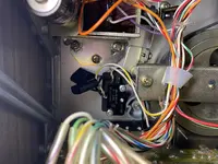
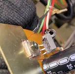
To get to this though, I did have to take one screw out of the switches on the back of the right tension arm and loosen the other. I then rotated it slightly to the side in order to get the pinch roller mechanism off. Initially, on reassembly, the capstan motor wouldn't run. I then took those switches off and verified they worked and then upon putting them back the capstan motor worked. I had read that they were easy to break if over-tightened so I figured I must have done that. But they seem fine. I don't know why they didn't work when after it being put back together initially.

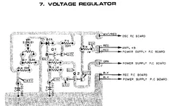
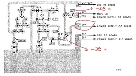
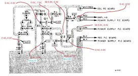
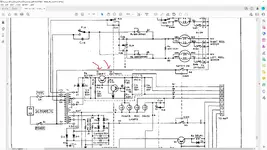
I was suspecting those 2 switches (called S2 & S3 in the schematics), but in the schematics - which is where I start to fall apart :-) it looks like one of the switches is for the capstan motor and the other is for the transports and both work. I could be wrong on those two switches though. But if seems they must be ok if the capstan and transports work?

I fixed a Teac 1500 that had the same capstan issue a week or so ago and gave that machine to my brother in law. I got a Teac 2300S (this one) off Craigslist knowing it had the pinch roller issue (and that I'll never see the 1500 again ha ha). I have a Teac 3440 that I've had for decades and it too had the pinch roller issue that I fixed in the last week or so while I could still remember how to do it ha ha.

This one - the 2300S - I didn't 'try' it before, but the seller had it all set up to push play when I got there and I just didn't have him do it. He pointed out the pinch roller issue. I'm pretty sure it was working before I worked on the stuck pinch roller but can't be positive. I doubt seriously he'd had it set up like that if it didn't have sound. It was absolutely totally unplugged during the work I did.

I have a service manual, but I'm way from being knowledgeable enough on those. It's like a massive failure as you said - no sound from tape or source, no vu activity at all (except lights). It just seems weird that it would go out just like that. I've looked and looked to see if something is inadvertently unhooked.

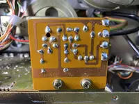
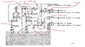
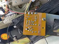
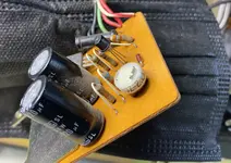
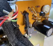
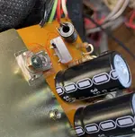
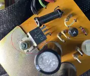
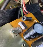
I believe there is only one fuse. There 'is' a small PCB board that sits right over the 'AC In' connection. Upon reflection :-) we did take one screw out of it and loosen the other and move it to the side. I don't see anything on it that looks broken, but he was moved. I'm not sure about the voltages - outside my experience level. I do have meters though.

Again, I appreciate your input.
 
Here are some images of the entire area showing flywheel and pinch roller assembly and switches; the Right Tension Arm Switches (S2 & S3) ; and close up of the board above the 'AC IN'
 

Attachments

  • 2023-01-26_11-42-46_153 - Copy.jpg
    2023-01-26_11-42-46_153 - Copy.jpg
    2.7 MB · Views: 6
  • 2023-01-26_11-42-35_889 - Copy.jpg
    2023-01-26_11-42-35_889 - Copy.jpg
    2.6 MB · Views: 6
  • 2023-01-26_11-42-23_341 - Copy (2).jpg
    2023-01-26_11-42-23_341 - Copy (2).jpg
    3.1 MB · Views: 6
The transport is behaving correctly, yes? If so then we don’t care about the tension arm switches, capstan or reel motors, pinch roller actuation, none of that. All of that is powered by the transport power rail and it’s all working. What’s not working is the audio stuff, and that has its own power rail or set of bipolar power rails. And so you need to measure at the power supply with a DC voltmeter to see if those are making power, and then also measure for AC volts and there should be no AC. That’s step one. And yes I see only one fuse and that’s just a main power fuse on the primary side of the main power transformer. That’s not the droids we’re looking for because if that was the issue nothing at all would power up.

BTW “lifters” are the two metal posts that move and lift the tape away from the heads during fast winding.
 
Yes, transport seems fine - thanks for confirming things we can move past.

I'm not sure how to exactly do what you ask.

In the image I've attached in this message - the voltage regulator board - next to the AC Input - I should attach negative of my meter to the case and then the positive to the various spots on the PC board (as shown) and see if I get say 23 volts as shown in the top right of the image? This is DC volts? Then try the other places say on this board?

Is that the board - you mean? Is that the process?

Not sure what that means about the checking AC volts and being zero.
 

Attachments

  • VR PC.jpg
    VR PC.jpg
    377.8 KB · Views: 4
I tried measuring the voltages on the Voltage Regulator board. I've not really done that before so was pretty timid about it. Nothing sparked.

In the diagram below, I think I mistakenly thought the GRN was the ground. Now, I'm not so sure - I think that means 'Green' wire.... I'm bummed now.

Anyway, these were the readings - minus 38 vs 23.5. Black was on the GRN - red on the test point. Black into Common on my meter. In AC it seemed to fluctuate and then go to zero.
 

Attachments

  • voltage regulator.jpg
    voltage regulator.jpg
    497.9 KB · Views: 4
I tried measuring the voltages on the Voltage Regulator board. I've not really done that before so was pretty timid about it. Nothing sparked.

In the diagram below, I think I mistakenly thought the GRN was the ground. Now, I'm not so sure - I think that means 'Green' wire.... I'm bummed now.

Anyway, these were the readings - minus 38 vs 23.5. Black was on the GRN - red on the test point. Black into Common on my meter. In AC it seemed to fluctuate and then go to zero.
Your common probe, the black one, should be probing the ground plane. That’s the black wires coming off the regulator board. So but the black guy there and re-probe the test points again with your red probe, as well as the green wire (with the red probe), and do the measuring both DC volts and AC volts. Report back.
 
Ok - thank you for that info!
Here are the voltages I found. It's possible I made a mistake - happy to recheck something.
 

Attachments

  • Voltage Regulator 2.jpg
    Voltage Regulator 2.jpg
    525.7 KB · Views: 11
Yeah I was going to say the same thing. It takes a little bit to acclimate to the schematics because there are, like, from the factory, 2 big sheets, but my pdf version splits each into 4-6 pages. And the regulator board isn’t labeled on the schematic. So once I found the section of the “transport” schematic that includes the regulator circuit I was able to determine the regulator board powers the audio and bias circuits. The black wires connect to the ground plane, the green wire is the unregulated power input to the regulator board, and the red and red/white wires are the regulated outputs. The red wires or at least one of them powers the audio amplifier circuits, and the red/white wire powers the bias oscillator. So @jamesperrett is right, R14 is where the power stops, I’d closely inspect the solder lands and maybe set your DMM to ohms and measure resistance across the collector of Q2 and the input or ‘+’ side of C14…these points circled in green:

C5E1AE46-F523-4578-BEB3-F20F37A27763.jpeg

It should be about 1Kohm. The reason we measure from the collector of Q2 to the input of C14 is because those points measure across R14, but also capture the solder lands and traces leading up to R14. If you get no continuity, then measure resistance across the exposed leads of R14. If you get about 1Kohm there then the issue is likely a damaged trace or cold solder joint. If you still get no continuity then I suspect R14 has failed. It is possible to have multiple causes, so just keep that in mind. It is also possible to crack these PCBs. The material is fragile. And a hairline crack is all it takes. So let’s see if we can zero in on where the fault and exactly what the fault is. It’s repairable.
 
Thank you two for your help!

I don't see anything obvious - I've attached some close up pictures.

The measurement between the two green marks - with no power on - ohm reading is 1K. like 1.0038 - something like that (on the 2k scale).

Even though I got a measurement above, I still did the measurement across R14 and also across R15 are both just a hair over 1K - similar to the above.
 

Attachments

  • Back 1 - Copy.jpg
    Back 1 - Copy.jpg
    3.1 MB · Views: 5
  • Front 1 - Copy.jpg
    Front 1 - Copy.jpg
    1.5 MB · Views: 5
  • Front2 - Copy.jpg
    Front2 - Copy.jpg
    1.3 MB · Views: 6
So I think at this point I’d do two things…I usually have to do a little shotgunning when I get to this stage because I’m not that smart. I’d reflow all the solder joints, and if that made no change, I’d remove and test the transistors, especially Q2, which is the smaller of the two. As a related aside the schematic and the PCB layout is a little confusing here because the labeling of the two transistors is flip-flopped on both…but Q1 is the 2SD317 the one where the collector ‘C’ connects to the trace with the green wire, and Q2 is the 2SC733, the collector of which is connected to the base ‘B’ of Q1. I’m suspicious about Q2 because you noted you have 0VDC there at the emitter ‘E’, and it should be around 3.0VDC, and instead you have about 0.7VAC and that ain’t right…could mean oscillation.

What make and model DMM do you have?
 
In looking at this a little more... And I couldn't see this at certain angles.

It appears that Q2 - I can see that he's been moved. It seems that he was bent over and attached to the board? Anyway, he's clearly come loose. Not the leads that I can tell, but the unit itself. See my pictures.

Could this be the issue? And how would I reattach him? I think it's acting as a heat sink, but can't be sure. If that's the case then it's not really part of the issue then? But, if it's some additional grounding then that's not happening..... it almost appears there is some metal sticking through it like it wants a ground?

Also, picture of my meter.
 

Attachments

  • 1 - Copy.jpg
    1 - Copy.jpg
    1 MB · Views: 6
  • 2 - Copy.jpg
    2 - Copy.jpg
    1.4 MB · Views: 5
  • 3 - Copy.jpg
    3 - Copy.jpg
    838.8 KB · Views: 5
  • 4 - Copy.jpg
    4 - Copy.jpg
    1.4 MB · Views: 6
  • 5 - Copy.jpg
    5 - Copy.jpg
    2.3 MB · Views: 6
Well, the part needs to be fastened to that heatsink, or the presumption is it will get too hot, and face an early demise. So there’s that. And the fact it has separated from its mounting tab may mean other mechanical failure which could equate to functional failure. And sometimes the mounting tab is also a ground connection and in some cases it needs to be isolated from the ground plane or bonded to the ground plane and I can’t tell from your pics maybe which is the case here. But no matter. You need a new one. I wouldn’t do anything else before replacing that part.

BTW your DMM looks to be a useful bit of kit. Glad you don’t have a cheapey one.
 
The transistor definitely needs to be replaced. I can't see how it can work in its current state. However, I would still expect to see volts on the base so it might be worth removing it and then checking to see if there are any volts where the base would have been connected. If there are no volts then you have another problem but if there is at least 20 something then you are probably OK.
 
I’m suspicious about Q2 because you noted you have 0VDC there at the emitter ‘E’, and it should be around 3.0VDC, and instead you have about 0.7VAC and that ain’t right…could mean oscillation.

I'm not suspicious of it at this point because with Q1 broken, there's no way that any volts can reach Q2 (I'm assuming that the green wire is the input and the red wire is the regulated output). As I understand it, everything goes through Q1 first and Q2 is part of the feedback circuit. Of course, it could be faulty but we would need Q1 to be working before we could tell.
 
After putting it back after my inspection, I went to verify my voltages. I found two places that I thought were zero, but did or do now have voltage. This was probably caused by my timidness in touching the probe - or maybe a loose joint I can't see. In any event, here is a new diagram showing the two new voltages in Blue. I'm not sure of the current route.

I've attached the schematic showing Q1 and Q2.
Thanks so much for help on it!
 

Attachments

  • Voltage Regulator 3.jpg
    Voltage Regulator 3.jpg
    523.9 KB · Views: 5
  • Skem1.jpg
    Skem1.jpg
    415.9 KB · Views: 5
Yeah sometimes one can be too timid…sometimes you have to apply a bit of pressure if there’s possibly some oxidation on the surface or whatever…you can’t always see it.

I have the schematic and the PCB layout. Looks like the corrected it on your schematic. Notice on your PCB layout it says the collector of Q2 is connected to the green input wire, but on your corrected schematic it’s Q1. Which is correct. The PCB layout has the part identifier swapped, Q1 for Q2 and vice versa. My PCB layout is the same as yours, but my version of the schematic is in error like the PCB layout. Anyway, Q1 is the 2SD317 at the input of the board, and yours needs replaced. That’s the first thing I would do.
 
As I look more closely, the schematic shows Q1 as 2SD317 and Q2 as 2SC733(Y)

The parts list for the voltage regulator shows - Q1 as 2SC733(Y) and Q2 as 2SD317-P. (Reversed)

The actual part put in at the Q2 location as shown on the voltage board is the 2SD317-P by physical inspection. So, I see why there is confusion. The schematic - you really can't tell which is Q1 and which is Q2.

I think this is what you were saying. I see that now. Some sort of typo in their service manual.

I'm trying to order now both transistors :-)
 
Back
Top