P-bass pickup question for the techs

famous beagle

Well-known member
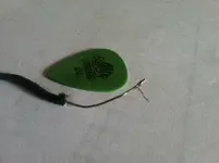
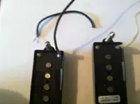
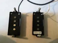
Hey everyone, I'm replacing the stock pickup in my SX P-Bass with a Seymour Duncan, and the short wire that connects the two parts came unsoldered (it did this on both pickups, so the wire is totally free now). I know I just need to solder it back to the solder spots, but I started to second guess myself after I stripped a bit of the end off one of the ends.

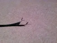
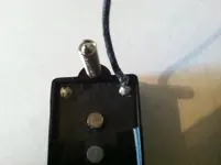
I noticed that there was one single bronze-colored wire and then some stranded silver color wires.

See the pictures:
Wire 1 is the way it looked after I stripped a bit from the end of the wire.
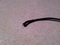
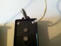
Wire 2 is the unstripped version (the way both ends looked when they came unsoldered).

So my question is what's up with these wires? Am I supposed to just solder the bronze single wire and not the stranded part? If that's so, it seems counterintuitive, because the bronze wire seems to be entangled with the silver ones anyway.

Or are these both (single bronze and stranded silver) basically the same wire?

Anyone have a clue about this?

Thanks!
 

Attachments

  • wire 1.JPG
    wire 1.JPG
    245.3 KB · Views: 68
  • wire 2.JPG
    wire 2.JPG
    239.9 KB · Views: 70
That wire should be a single conductor. You'll have to trim it to even it out, then lightly solder the wire (referred to as tinning) before soldering it to the pickup bobbin. Be careful not to overheat the bobbin.

Bassically, Michael
 
Ok, so I need to solder just the bronze single wire and make sure the stranded doesn't touch. Is that correct?

Thanks
 
Ok, so I need to solder just the bronze single wire and make sure the stranded doesn't touch. Is that correct?

Thanks

If the pickup hook up wire has come away from the pickup you need to solder the hot to the hot connection on the bobbin and the shield/ground to the ground connection. Essentially one end is connected to the start of the pickup coil and the other to the end. The ground connection is required to keep noise to a minimum and retain continuity. If it confusing you at present you should put up a picture of the bottom of the pickup bobbin and we may be able to point you to the correct solution.
 
Can you snap a picture of where they came off? Is it the wire I have shown below? Kind of wondering if they bothered with a shield connection if it's that wire.

Yes this is the exact wire. Here are some more pictures.
 

Attachments

  • both parts - back (with disconnected wire).JPG
    both parts - back (with disconnected wire).JPG
    163.7 KB · Views: 55
  • black wire - back.JPG
    black wire - back.JPG
    150.1 KB · Views: 52
  • white wire - back.JPG
    white wire - back.JPG
    161.5 KB · Views: 50
  • two parts - back.JPG
    two parts - back.JPG
    188.4 KB · Views: 53
Last edited:
Like I said in my first response, that's a single conductor wire, cut the ends off, strip back the cover, tin the leads and carefully solder it back to the bobbins. Use a 20-30 watt soldering iron.

Looking at the original photo, it looks like you might have broken a piece of the pickup wire (the single bronze colored wire) that's wrapped around the output outlet. Do you have a DVM to test the pickup for DC ohms to check that it still works?

Bassically, Michael
 
Last edited:
ok so thats the neck pickup. Follow the wiring diagrame posted earlier so you have this....

prcision 233.jpg

The white is your hot and goes to the 1st lug on the pots. The black is the ground and should go to the casing of the volume pot and then to the casing of the tone pot and on to the jack...
 
Like I said in my first response, that's a single conductor wire, cut the ends off, strip back the cover, tin the leads and carefully solder it back to the bobbins. Use a 20-30 watt soldering iron.

Looking at the original photo, it looks like you might have broken a piece of the pickup wire (the single bronze colored wire) that's wrapped around the output outlet. Do you have a DVM to test the pickup for DC ohms to check that it still works?

Bassically, Michael

You're telling me this is a single conductor wire, and others are telling me that the bronze wire is the signal, and the silver braided wire is the shield.

If I'm understanding you correctly, you're telling me to treat it all (silver and bronze) as one wire, trim the bronze back, and solder it all together to the points. That's no biggie at all.

The thing is, though, it doesn't seem as though that's the way it originally was. Otherwise, why would the bronze wire be sticking out on its own for a good 1/4" or so?

At this point, I may just try it one way or the other and see if it works. If not, it won't be too much trouble to try it the other way.

I do have a multimeter to test it.

Thanks
 
ok so thats the neck pickup. Follow the wiring diagrame posted earlier so you have this....

View attachment 83514

The white is your hot and goes to the 1st lug on the pots. The black is the ground and should go to the casing of the volume pot and then to the casing of the tone pot and on to the jack...

Thanks for the response, but that's not exactly what my pickups look like. They don't have the middle wire between the two solder points.

I know where the wire should go and how to wire in the pickup.

The only thing of which I'm not sure is this:

Do I solder just the bronze wire to the solder cup and make sure the silver braid is not touching the solder point?

Or do I (as Michael4Bass seems to be saying) treat the bronze and silver braid as one wire and solder them both to the solder cups?
for the wire that simply connects the two coils I'd say either way would work ..... can't imagine it matters ........ it's just connecting the two coils and nothing there is connected to any shielding.
 
for the wire that simply connects the two coils I'd say either way would work ..... can't imagine it matters ........ it's just connecting the two coils and nothing there is connected to any shielding.

Thanks. That seems to make sense. I think I'll just give it a shot one way and see if it works. If it doesn't, it's not hard to try it the other way.
 
for the wire that simply connects the two coils I'd say either way would work ..... can't imagine it matters ........ it's just connecting the two coils and nothing there is connected to any shielding.

True, but to be properly shielded the ground or black wire must maintain continuity through the instrument via the pots and jack socket which is why I described it that way. TBH if it were me I'd replace the wire altogether but as you say if it only makes contact where it needs to it won't matter.
 
True, but to be properly shielded the ground or black wire must maintain continuity through the instrument via the pots and jack socket
yes but on those pickups there is no way for that to happen since there is no place to solder a shield. It can still be that the shield in connected elsewhere and is connected from the other end ........... but you can clearly see that the shield is gonna get interrupted between the two coils and there is nothing for it to be solder to.
 
Your original picture of the wire and the description made it sound as if were a shielded wire with an outer shield and single inner conductor. As this thread moved forward with some more information it appears the wire simply connects the PU's together to make a series connection. Perhaps the reason for the bronze and silver colored wires is that it was originally tinned in a sloppy manner leaving some of the strands untinned (bronze/copper). You can simply twist the ends up and re-tin the wires and solder it to the PU's or even a new piece of wire of the same length with the ends tinned should be OK. If it's a passive PU setup in the bass no harm done if it isn't right, but only may affect the way it sounds which may happen if the PU's are connected out of phase. Follow the wiring diagram that you got with the PU's and you should be OK.

I just pulled some more insulation off the untouched end, and I think y'all are right. I think it's just a single stranded wire, and that bronze wire is just a stray, untinned strand. It's a little strange though, because I've pulled back a good 3/8" or so from one end and can't see the end of the tinning. (In other words, I can't seem to find the copper section that hasn't been tinned.

In fact, I just realized it was push-back wire, and I pushed back a bunch of insulation on both ends and can't find the end of the tinning. It appears that the entire 3 inches of wire (or so) is tinned. (see picture) Weird.

At any rate, I'm pretty sure it's just a single stranded wire (as Michael4Bass has said), so I'm going to just try that.

Damn ..... could have had this done in 3 minutes several days ago when it happened and I had all my tools out. :)

Thanks everyone.
 

Attachments

  • tinning.jpg
    tinning.jpg
    2.1 MB · Views: 25
Did you meter the coils yet? I'm very much afraid that Michael could be right about the origin of that single copper strand. Even just look at the pickups. Are there similar such "strands" connected to the other solder lugs? maybe kinda coming from the other side of the bobbin? I can't tell from your pictures.
 
Did you meter the coils yet? I'm very much afraid that Michael could be right about the origin of that single copper strand. Even just look at the pickups. Are there similar such "strands" connected to the other solder lugs? maybe kinda coming from the other side of the bobbin? I can't tell from your pictures.

I can't see any traces of a single copper strand coming from any of the solder blobs on the pickups.

I can't meter the pickups until I resolder the connecting wire, correct? I plan on doing that tonight.
 
You can test the pickup by setting your meter to the 20k ohms range and measure across the two expose solder lugs. One is the start of the coil and one is the finish. That will at least tell you if the coil is intact and will give you a reading of the DC resistance of the coil.
 
Back
Top