MS-16 story

The relay replacement is good

I got a little time to put in the Omron G5v-2-H1-DC24 relays as replacement for the original NEC. I can say that they work fine.

I've only found time to replace the relays and blown CMOS ICs on 6 of the 16 cards so far. Just too many other things to do. But, I thought to get this info in the thread should anyone be interested.

I use a good 15 watt iron and a typical solder sucker from RS. The metal shield that fits over the relays comes off easily as do the relays if you get a good "suck". If not then a little reheating goes a long way. Just be gentle.

Pulling the dead IC presents a greater degree of work as that on is 14 pins and the other 16. All in all it takes 30+ minutes per card to remove the shields, relays, dead ICs and then install sockets, new relays and replace the shield and socket the ICs.

Don't leave the shields off as that they help prevent crosstalk and stray hum pickup. They after all switch the heads to the input amp and record drive amp.

As always work carefully and stop when you find your attention not where it should be. I get tired and need to do something else....

My plan has been to work on this deck in stages. Stage 1 is to get it all working and calibrated to spec.

Stage 2 will be to change the bias level to allow calibration to 370 nW/M.

Stage 3 will be to upgrade opamps, EQ caps and feedback resistors.

Regards, Ethan

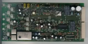
PS here is a photo of the relays and sockets in place but before putting the shields back on or replacing the ICs.

I have a spare card from TallDog (thanks again) and I note that someone before him replaced the relays and an IC. They left the shields off and installed the socket backwards....Oops! Let's not do that to ourselves.
 

Attachments

  • card-3-a.jpg
    card-3-a.jpg
    30.9 KB · Views: 91
Nice work, Ethan!! ;)

Frankly I'm impressed with 6/16!

What is the advantage to using sockets? Is it:

  1. Avoid heating the IC when it gets installed
  2. Easy to change out if problems arise or to trial other types
  3. Both of the above

Its interesting that on my 58 cards, only one of the relays is covered...:confused: I can't tell if one cover was removed at one point or not. When I cleaned my relays I pulled the one cover off of each and put it back. Wasn't really a big deal, and made a big deifference in the machines mechanical response to monitoring source changes (i.e. switching from input to sync to repro).

I'll be very interested in stage 3...:D;)
 
It is door number 2. The replacements now are logic so no need to swap out. Just need to replace if they fail again. Something blew them up....

For phase 3 sockets will allow trying differing devices. I'm planning on a side by side test of the usual suspects.

4558 - As installed by tascam
NE5532 - an old but good standby
BB OPA 2132 - I've used them in a tascam 32 halftrack and liked them
LT 1458 - as suggested by Jim Williams.

Phase 3 will have some cookbook details provided in this thread. Pull the IC, Install sockets, install bypass caps, plug in new IC, check calibration.

Ethan


Nice work, Ethan!! ;)

Frankly I'm impressed with 6/16!

What is the advantage to using sockets? Is it:

  1. Avoid heating the IC when it gets installed
  2. Easy to change out if problems arise or to trial other types
  3. Both of the above

Its interesting that on my 58 cards, only one of the relays is covered...:confused: I can't tell if one cover was removed at one point or not. When I cleaned my relays I pulled the one cover off of each and put it back. Wasn't really a big deal, and made a big deifference in the machines mechanical response to monitoring source changes (i.e. switching from input to sync to repro).

I'll be very interested in stage 3...:D;)
 
wow, I haven't visited Home Recording for quite a while, but as an MS16 owner, I'm glad I just did. This is the best thread on the MS16 that I can remember.
 
Moving Forward - progress report

Got some time to finish up those channel cards over the last 3 days. This involved pulling the 4000 series ICs (U5 and U6), installing sockets in their place, re-populating with new ICs, pulling the old relays and their covers and installing new ones. This all takes about 30 minutes a card plus or minus.

Tonight I got them all back in and ran a basic function test. This involved inputting a test tone into the channels one by one and listening to the input and sync functions. That seamed to go well so I switched over to record and went channel by channel testing input, sync and repro. Then rewind and see what got layed down and to verify that both the sync and repro head worked.

The end results are that 14 out of the 16 channels work :) Channel 6 card has a problem that causes the bias amp (U7) to heat up. That could be bad... And channel 16 had a problem. I ran out of relays (one shy of what I needed) so 16 only had one replaced. I don't think that it is the relay....

I'm looking for a few more spare channel cards if you happen to have any PM me. I'll take non-working cards too in order to scavenge the bias amp.

In any case debug on these 2 cards will have to wait for an extender card to show up. Could use one of those too.

All in all this is very good progress - I'm excited.

Regards, Ethan
 
hey Ethan

I found a couple more cards that may or may not work. I'll get off my lazy ass and send them with the mrl tapes that I still haven't sent. Can't help you with the extender card. I wish I had one. BTW I just put a new pinch roller on my ms16. It was NOS. This means I have a couple of shiney rollers if anyone needs them.


Thanks. Send me your dead cards. They will make a test bed for mods and side by side mod testing.

I was able to fix channel 6 last night. It took a bit of "solder wire here, reinsert card" to get the signals out for measurement. Turns out it was a burnt trace on the PCB from Q16 emitter to ground. This trace feeds ground to other places on the PCB so the symptoms were not very obvious. Plus the trace was hidden under a cap.

THis just leaves channel 16 card to fix. Looks more like a logic problem.

I'll be needing that MRL RSN (real soon now). Thanks again for everyones your help.

Ethan
 
MS-16 Mod #1 - switching input to tape time delay

I'll most likely start a new thread to catalog the mods for my MS16 channel cards (which would include the 58). No need to wade through 6 pages to this one. But till then here is the first one.


There is a built in delay when switching source from Input to tape (sync or repro) and back again. This feels sluggish to me and takes a bit of time.

This delay is caused by an RC network in the control signals to the FET analog switches. The resistors of the network act to delay the charging and discharge of C30 for the Tape FET switch and C32 for the Input FET switch.

MOD: remove C30 and C32.

RESULTS: Switching from Input to Tape and back again is crisp and immediate.

One could reduce the value of the caps from their speced 4.7 uF to a lower value to retain some delay in switching.
 
To supress switching noise in Punch-in/out

What is the purpose of the delay?


The delays are introduced to prevent switching noise during punch-in and out. The delay from sync to input is on the order of 350 mS (1/3 of a second) and from input to sync is 600 mS.

Because of the large time constant this delay also causes a gradual decrease of one signal to the other with some period of overlapping where both sync and input are coming out of the channel card.

I don't do a lot of punching in so getting rid of any (if any as that there are other noise supression circuits) is not big on my list. But rapid switching is.

One could do 2 things as a mod to the mod. First is to match the caps C30 and C32 values to each other so that the delays are equal.

The other is to decrease their value (with matching too) from 4.7 uF to (oh say) 1uF. This would preserve some noise elimination while decreasing the delay.

Note that this is not a on-off-on type of delay but rather a gradual turn on and off.

The process is described in section 5-8-5 and figure 5-18 in the MS-16 manual and section 5-7-5 and figure 5-23 in the 58 manual.

--Ethan

PS my machine came modded so I looked into why I was missing 2 caps from each channel card.
 
Cool...thanks.

Now I remember that from the manual. When in doubt, read (and re-read) the manual. :)

I like learning what components do in different scenarios, and the larger the cap increases the delay because it takes time for the cap to become charged and the current to "spill over" to the downstream path right?

Thanks.

Almost.....

No spilling over in this case. The resistor limits the current that can pass (current is the number of electrons per second). The cap value is the size (if you will) of the cap. So a limited number of electrons per second going into a cap will rise to the source voltage at a some rate. More electrons per second and it takes less time. Bigger bucket (er cap) takes longer to reach the source voltage. And the reverse (less electrons more time).

So as the voltage rises (or the voltage decreases when you ground a charged cap through a resistor) it gets to the point were it is greater (or less than) the turn on (or off) voltage of the fet. Thus the fet turns on and allows the audio signal to go through it or turns off and blocks the audio.

If you looked at the voltage of the cap with the scope you would see a ramp. If you also looked at the FET you would see no audio passing as the voltage ramped up till it crossed into the turn on voltage then you would see a little audio then more then more as the cap voltage increased till teh FET was fully on where you would see the full audio signal.

This is just a switching mode of operation. If you wanted the fet to be an amplifier you would need to keep the ramp voltage in the linear region. Little change in the ramp gives large change in fet conductivity.... In this case we are just slamming it on or off.


--Ethan


http://en.wikipedia.org/wiki/Resistance-capacitance
http://en.wikipedia.org/wiki/Field-effect_transistor
 
OK Now

So all channel cards are working - Turns out that it pays to not overlook the basics. I Stuck the card on the extender and started through some tests to see exactly what was not working. I listened to a tone on the input then one on tape through the sync head. OK so far, then the tone through the repro head. No problem.

Off to record mode. Listen to input tone - OK. listen to sync - OK. Listen to repro - No signal..... Rewind and listen to tape again - the previously recorded signal (don't do this with your MRL Folks!) is gone - Thats good, it means that the erase head is working.

Blinding flash of light and thunder as an idea strikes me - back to basics - What is the position of the record level pot? Shazam - the record level is at 0 - turn that pot up and we have a recorded tone. This card had no problem other than the record level was at 0.

All channels work now it is time to get on to calibration.

A special thanks to all those folks who gave do freely!

Regards, Ethan
 
Wow, awesome work man! get that sucker calibrated and get some tracks recrorded!

AK

Soon!

I'm waiting on an MRL tape coming in the mail (Thanks to Tall Dog) to get mor calibration done.

Currently I've cal'd up the output levels, meter and peak LED. Not much more to do till the MRL arrives.

It is interesting to note that the cards appear to have been cal'd for an output of 0.7 V which is about 6 dB too much. Once I got them down to 0.316 V the meter and peak led were close. Some were right on. The cards appear to hold their cal very well.

-Ethan
 
Just in

Mrls are on their way! A couple of cards too. Now you have some spares.

Thanks! I got them. I'm just back from some sailing in the San Juans. It will take a while to get it all going again. I'll be bring the boat back down the coast next weekend so that is out too. Just a few nights this week then sometime next week.

I recall that you said that the MRL need Baking - Just checking on my memory.

--Ethan
 
Back
Top