mrbowes
New member
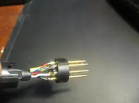
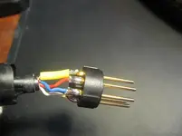
I have a PZM mic that was originally designed to be remote controlled and has a 5 pin connector (MPC 67_RC). I'm trying to make the mic end with a regular 3 pin XLR.
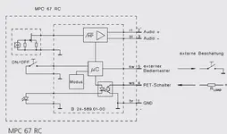
I'm a newb when it comes to reading schematics and am wondering if anyone can help me identify which colors represent the different leads on the schematic. Trying to figure out which colors need to be connected to make this work with regular XLR.
I'm a newb when it comes to reading schematics and am wondering if anyone can help me identify which colors represent the different leads on the schematic. Trying to figure out which colors need to be connected to make this work with regular XLR.