MCI JH-416 Story...

  • Thread starter Thread starter sweetbeats
  • Start date Start date
lets begin with the 2nd : from under the desk you can see the screw and the hollowed area ...
4th: the leg ( 7,5x5cm ) and the L shape for your screwhole in your console ...
1st : two cables goin to the mic , blue left and red right and as i can measure , follow the red cable to the brown bridge , i think yours is broken.
3rd is a detailed pic of the talkback mic.

hope this helps !

Cadde
 
Very much. Thank you so much.

So I think I understand that the legs are 5cm wide, and then 7,5cm "tall" or thick...that would make the square inside the leg assemblies 68cm - (7,5cm x 2) = 53cm by 68,5cm - (7,5cm x 2) = 53,5cm...do I got it??

And it looks like maybe somebody added a second 'L' shaped bracket to yours? The one in the picture IMG_0648? Not a bad idea.

I'll do some tracing of the wires that I still have on mine. At the very least your pictures of the wiring help me see that there is a chunk of the terminal strip missing on mine and helps me understand the size of the work to do.

Thank you again so much.

Let me know if/how I can help you.
 
And one more thing while I've (hopefully) got you here...

Can you help me with the wire colors and where they go on that terminal strip?

I have numbered them from 1 to 6 in the attached picture below.

It looks like:

1. orange wire coming from harness, red wire going to SOLO light AND red wire going to talkback mic?
2. black wire coming from harness, red wire going to SOLO light
3. Ummm...those two brown wires coming in that come from the harness, annnd...what going out?
4. Something coming in from the harness? And the blue wire going out to the talkback mic?
5. Something coming in from the harness? And a brown wire going to the METERS light?
6. Something coming in from the harness? And a brown wire going to the METERS light?
 

Attachments

  • meter_bridge_terminal_strip.webp
    meter_bridge_terminal_strip.webp
    47.8 KB · Views: 115
So I think I understand that the legs are 5cm wide, and then 7,5cm "tall" or thick...that would make the square inside the leg assemblies 68cm - (7,5cm x 2) = 53cm by 68,5cm - (7,5cm x 2) = 53,5cm...do I got it??

Yep !


We´re making the world a bit better ....

A american friend brought me into recording , after he produces my first ( and only ) Album.

I´m glad to help as good as i can.

Cadde
 
somebody added a second 'L' shaped bracket to yours? hhmmm ....could be ....

i would likely builda steel frame ... to me are the woodstands the weakest points ...

Cadde
 
Hey, just for fun here are some pics of the Power One 24V power supplies...again, there are four of them which will make two 24V bipolar supplies.

I'm looking for used rack mount chassis to load them in. These things are beefy.

Overkill: each supply has three 13,000uF caps for filtration. Yup...that's 38,000uF of filtration per bipolar supply.

Here's one-o-them:

IMG_2385_2_1.JPG


IMG_2386_3_1.JPG


For perspective, here it is with my dead Alesis Quadraverb:

IMG_2387_4_1.JPG


IMG_2388_5_1.JPG


Also, I'm thinking more and more that it would be best to have the patchbay modules mounted to separate faceplates rather than one...I can imagine it being a PITA to get to the backside of one jack if all the jack blocks were mounted on one plate vs. being able to just pull one module.
 
Last edited:
Probably a good plan re: patch bay faceplates!


Those power modules have some punch for such a small footprint, small cans for those 13000ufs too! Looks like they'd rack up pretty well, how tall are they, 2U-ish?
 
Probably a good plan re: patch bay faceplates!


Those power modules have some punch for such a small footprint, small cans for those 13000ufs too! Looks like they'd rack up pretty well, how tall are they, 2U-ish?

Yeah, the footprint is about 16" x 5", but they are about 4" tall so 3U is needed for rack mounting.
 
hi , all i can see is 1+2 going to the light above the talback mic ,
3+4 to talkback mic and 5+6 going to the light under the talkback mic !

Cadde
 
hi , all i can see is 1+2 going to the light above the talback mic ,
3+4 to talkback mic and 5+6 going to the light under the talkback mic !

Cadde

Thanks again, Cadde...that is helpful. If you have a chance I forgot earlier to ask for two more measurments: the distance between the very front of the mixer and where the leg starts, and the amount of overlap of the leg and the side panel. Does that make sense?
 
Thanks again, Cadde...that is helpful. If you have a chance I forgot earlier to ask for two more measurments: the distance between the very front of the mixer and where the leg starts ? and the amount of overlap of the leg and the side panel. Does that make sense?


1. and where the leg starts ? sure , stay tuned ...
2. amount of overlap of the leg and the side panel ? excuse me i dont get it ...

in my imagination you´ll going to build the side panel first with the dimensions formerly stated ( BIGGER IS BETTER / STRONGER ) and you´re , ääähhh , ready to attach it to the console. And again, i would build it with the strongest/best wood i can get , cause it seems/ feels so weak. Maybe over the 40 years the wood became a bit weak over here , but if i´ll have to build new stands , they´ll be out of steel.
for me it seems youre going to original as can be , or ?

the most customers / so called musicians / even producers dont even know what brand of the console is , when they see her the first time ... ( whats that ? :eek: )

So , if you build the stand stronger, propably only the real oldtimers will notice.

:-)

Cadde
 
excuse me , i´ve been a few days in denmark , so the distance from the very beginning of the mixer and the leg is 24,5 cm.

hope this helps ...

cadde
 
Thanks again, cadde.

By "amount of overlap of the leg and the side panel" I meant like how far from the TOP of the side panel to the TOP of the leg, but that is hard since the side panel is slanted on the top. Maybe just how many cm's from the top of the side panel to the top of the leg at the front of the leg assembly? I hope that makes more sense. I'm trying to figure out how far the console "sits" down into the leg assemblies.
 
Just a passing note here...cleaning the studio up after a maelstrom of hither and thither projects...focusing on getting the Ampex MM-1000 up to par and actually kind of putting the MCI console aside for now. I did get the spring-loaded ADC punch tool for the ICON-96 QCP punch panels I'll be using for cross-connecting the cabling and I have all the patchbay hardware now too except for the custom faceplates. I decided to go with individual faceplates instead of one big one but I'm not ready to have those made up yet. But all the individual bays are identical vintage and style ADC bays just like the factory JH-416 bays but with my custom configuration...the last 1U patchbay I bought is actually 144 point...the jack blocks have 72 jacks each in one row of 24 jacks and then a 2 x 24 row of normalled jacks. So the top three bays will be 2 x 24 and the bottom two bays will be 1 x 24 + 2 x 24. The top three bays are normalled connections to/from the I/O modules out to the studio while the bottom two are supposed to be other miscellaneous patch points mainly to/from the master modules as well as the "tie-lines" (where you connect all your outboard gear that doesn't tie directly to tape outs, direct ins, etc.). The JH-416A has a five-bay 244-point patchfield that increased to six bays and 288 points for the "B" version. Some have found creative ways to tack on another bay on the original JH-416's to get additional tie points but I don't like that...kludgey. So my solution gets the additional 44 points within the five bays and still leaves the nice recess below the patchfield for the unused patch cables and such. Nifty. Yes it will be more dense but the reality is that MOST of the points are normalled anyway, and I'll have the option of normalling or non-normalled tie lines with the bays that will have the 72-point jack blocks and all of that can be configured/reconfigured at the back of the console with the slick and easy ADC QCP panels...strip and punch, no soldering de-soldering...need to change something? Yank, strip, punch, done.

I don't recall if I mentioned this above or not but Redco has the best price on the exact cabling I need to recreate the harnessing...Gepco makes it, 22AWG twisted pair with drain and 100% foil shield, and they have for a better price than anybody, AND it comes in 8 or 10 colors and is sold by the foot so I can even recreate the harness with the same color scheme as from the factory.

Anyway, whilst cleaning up in the studio I reassembled the meter source switching module that I took apart eons ago to clean.

Here it was before (the one on the right labeled "meters"):

IMG_0097_1_1.JPG


IMG_0098_2_1.JPG


And here it is now...not perfect but my intention is not to make it "perfect"...I'd have to rescreen, repaint, etc. Not going there:

IMG_2849_9_1.JPG
 
Last edited:
WOW, this thing looks awesome Sweetbeats! Wish I could find one of these in working order for an affordable price! you are obviously much more adept to working on these sort of things than I. Although, I'm considering doing a recap job on my little M312. We'll see. Good luck with this thing, looks beautiful. -John
 
Check this out...

I've been worried about how I as going to mount the four 24VDC Power One supplies I got to make up the two bipolar 24V supplies needed for the relay buss and the audio buss...

Well check out what I found at my local electronics shop:

IMG_3016_24_1.JPG


Yep...that's an old rack-mount PC case...like an old server case from back in the EDO RAM days. The thing is about 22" deep, 4U in height and by itself weighs over 50lbs. Its pretty heavy duty and as you can see they used lots of yellow zinc plated steel which is nice. This was not a cheapy case when new and its appearance is even mildly reminiscent of the cases of the OEM supplies for the JH-400 mixers, at least I think so.

It will (of course) require some extensive mods but at least it is a good starting point and it will work. I'll be gutting it and reconfiguring the backplane to be a fan-mount panel. I'd like to use the two fans from inside the case and regulate them so that they spin gently and quietly...the intake at the front has a foam filter. Where the keyboard and power switches are at the front will be a great place to mount some indicator lamps...I'll get blue neon panel lamps which will blend nicely with the factory look on the OEM supplies. I'll move the switches behind a door that currently houses the drive bays. I'm thinking of just building in a manual soft-start circuit, like a two stage switch and some kind of timing indicator for when the caps are charged.

Anyway, lots of work down the road on this, but it will WORK and work nicely for the Power One modules.

More pics of it:

IMG_3012_20_1.JPG


IMG_3013_21_1.JPG


IMG_3014_22_1.JPG


IMG_3015_23_1.JPG


IMG_3019_25_1.JPG


IMG_3020_26_1.JPG


IMG_3021_27_1.JPG


I really don't think this thing saw much uptime...you can always tell alot about the life of a PC by the dirt inside and there isn't hardly any on this one even in the nooks and crannies, and the exterior is relatively spotless. And, oh yeah...$30. That's a good deal even for a used rack-mount PC case and this is one is pretty nice.

And check out what ELSE I found while I was there...another ADC TT patchbay. This is just like the other one I got for the bottom two bays...72-point, but this thing is COMPLETE and SPOTLESS...couldn't believe it. I've never seen anything like this at that shop's boneyard...

IMG_2997_11_1.JPG


IMG_3000_12_1.JPG


IMG_3004_14_1.JPG


IMG_3005_15_1.JPG


IMG_3009_17_1.JPG


IMG_3010_18_1.JPG


And...oh yeah...

IMG_3011_19_1.JPG


I thought for sure the decimal was in the wrong place. I don't really NEED another of these but for mint condition I couldn't pass it up. It may end up being needed, I don't know, but for $10??? Do you know how much these things went/go for new????

And THAT'S NOT ALL! Anybody need a TT patchbay? I'm yer guy. FOUR 72-point SWITCHCRAFT TT patchbays, PC board type with cinch connector termination...these also LOOK NEW:

IMG_2984_1_1.JPG


IMG_2985_2_1.JPG


IMG_2987_3_1.JPG


IMG_2989_4_1.JPG


IMG_2990_5_1.JPG


IMG_2991_6_1.JPG


IMG_2993_8_1.JPG


And...Oh yes...

IMG_2995_10_1.JPG
share/pictures
 
Last edited:
Ohhh I hate you! :D

GREAT scores there and especially that computer case! You're right, first thing I thought was that the color is pretty close to the MCI "van dyke brown" IIRC!

Since your Sountracs seems to have come to beautiful fruition, I guess it's on to the 416 now eh? :D ;) :D
 
I'm doing some work on the patchbay element of this project.

I'm finalizing the design of the custom mini-rack panels that will be fabricated by Front Panel Express that will mount the ADC TT jack blocks...just making sure my design is right before I pull the trigger and place the order.

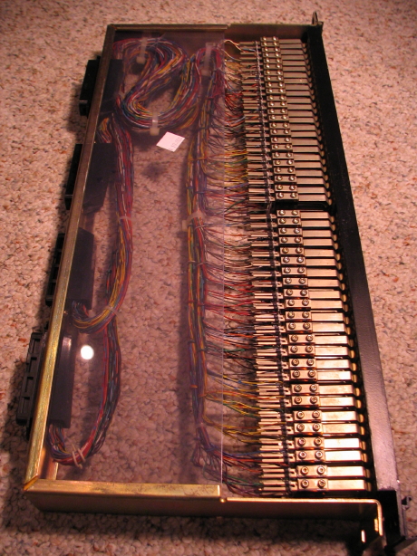
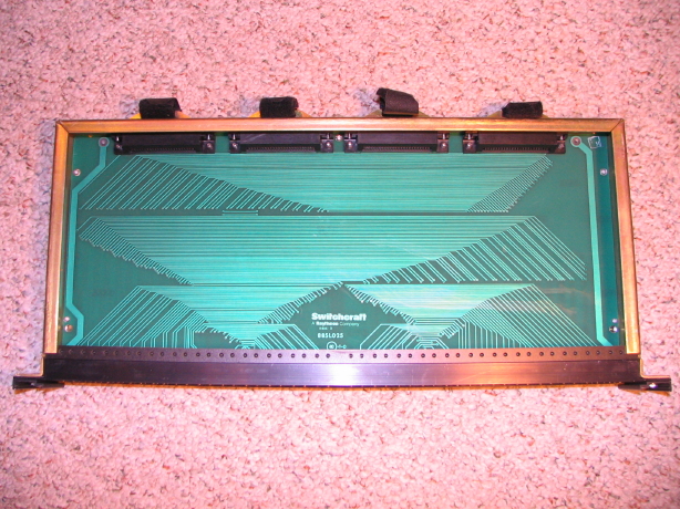
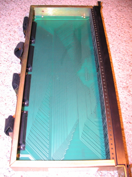
The ADC patchbay featured in my last post has been disassembled (removed the jack blocks from the frame) and I've stripped all the wire-wrap wiring from both blocks. That's nearly 400 little wires to unwrap from each 1U bay.

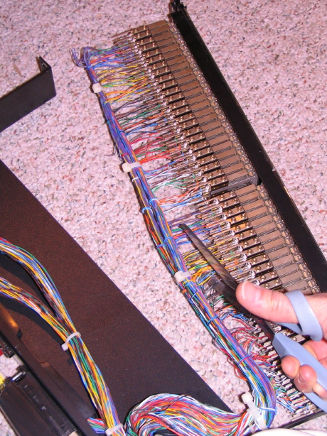
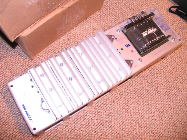
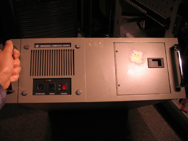
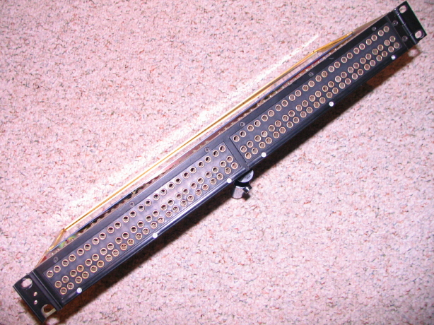
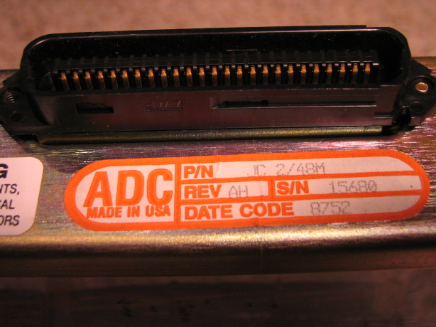
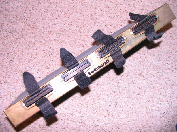
I just unboxed another identical but even newer ADC bay I got for cheap sometime last year to do the same thing. I'm stoked. My JH-416A will be outfitted with a basically new patchfield. These are nice bays. So nice that it totally feels wrong to do this:

IMG_3420_5_1.JPG


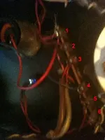
I believe this particular unit is essentially unused and there I am hacking into it with a pair of scissors. I have to remind myself that the wire and wire wrapping in general is not ideal for audio. The wiring is, like, 28AWG or smaller solid core CAT3 telco wire, and eventually the wire wrapped on the jack terminals can oxidize and cause trouble. That's why I'm yanking all the CAT3 and when it comes time to build up the harnessing I'll be soldering everything and using Gepco 22AWG shielded stranded install cable.

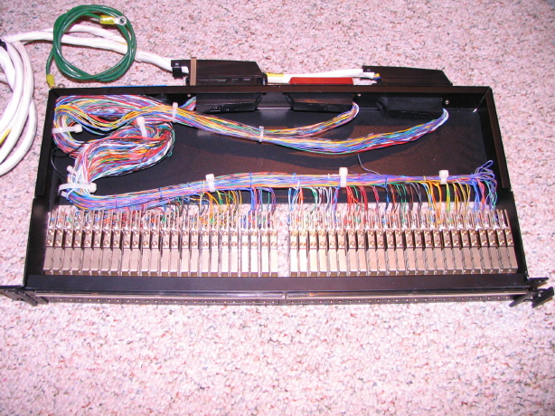
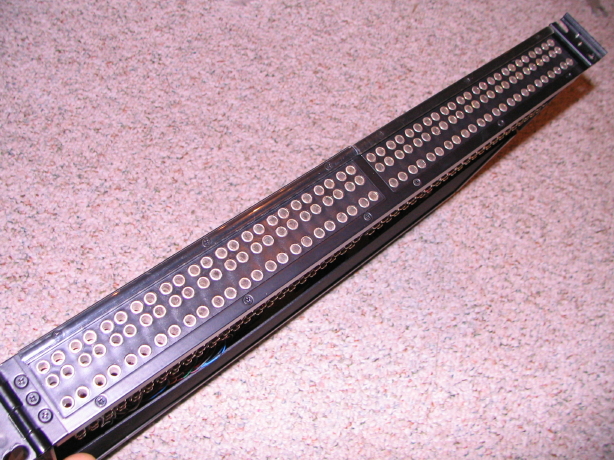
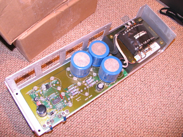
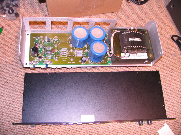
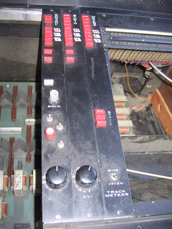
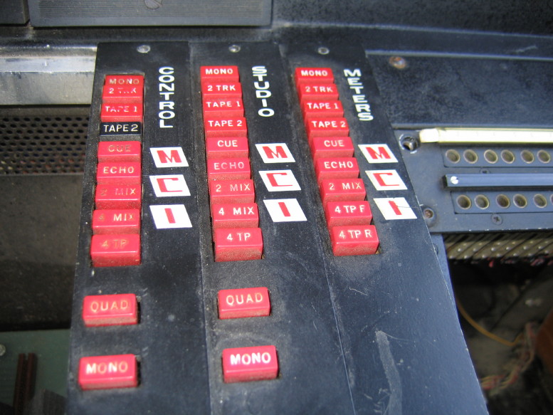
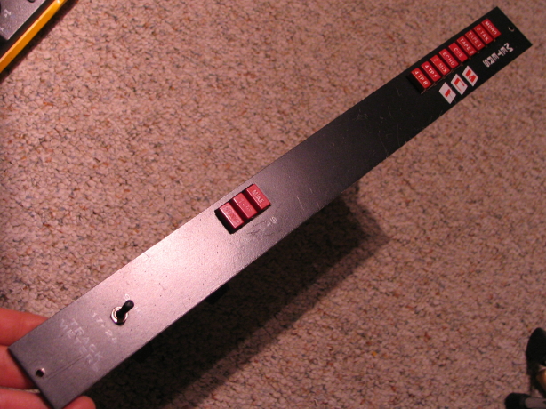
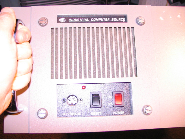
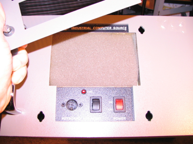
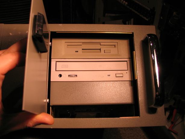
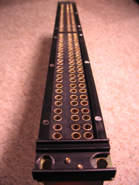
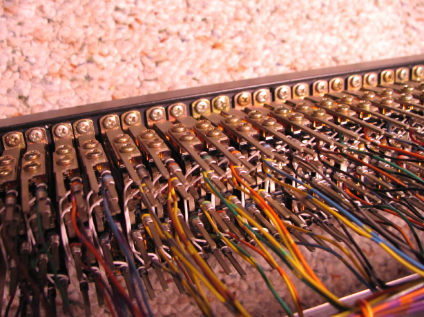
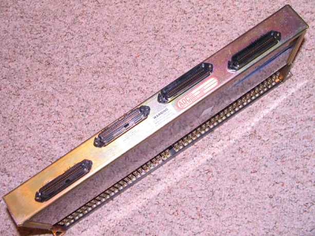
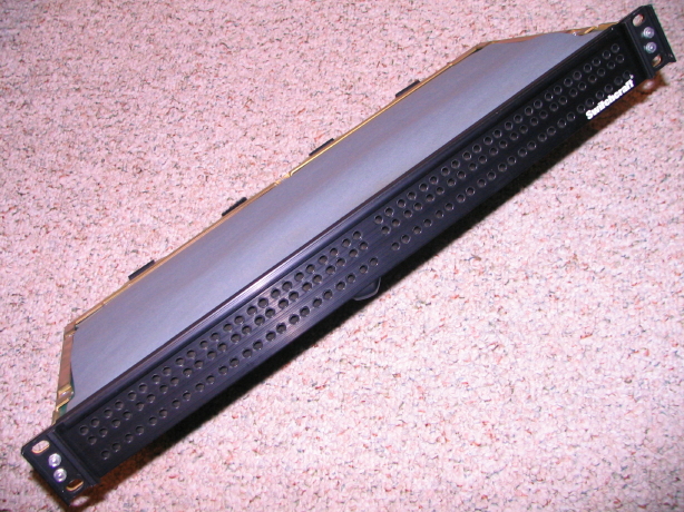
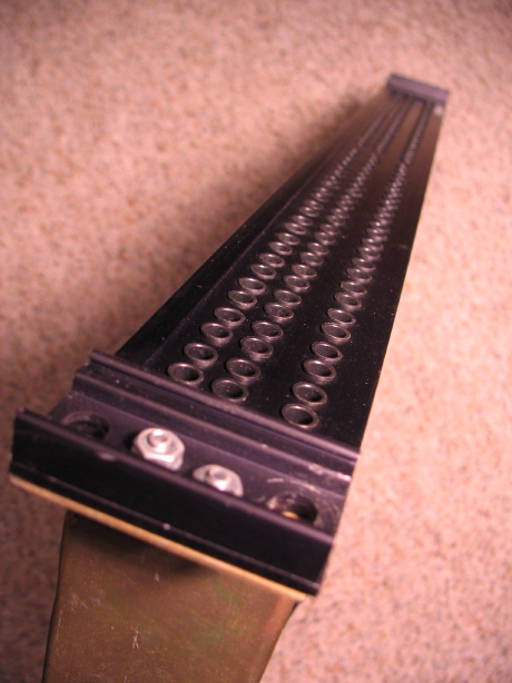
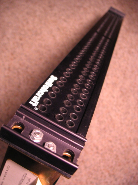
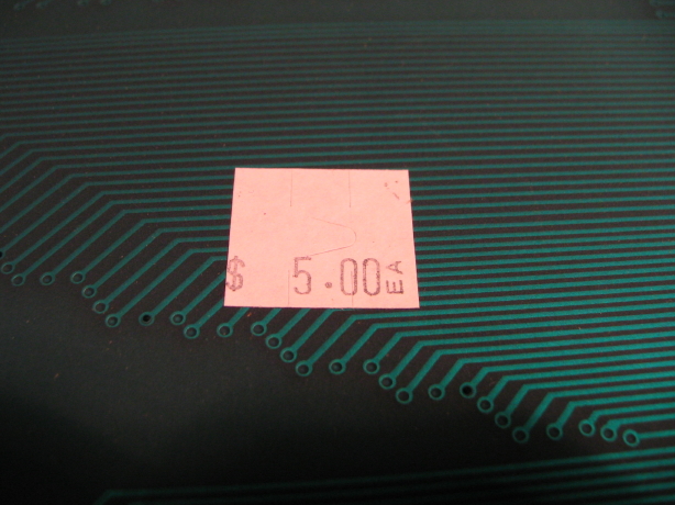
Here's a few more shots of this most recent patchbay:

IMG_3413_1_1.JPG


IMG_3414_2_1.JPG


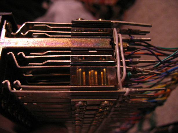
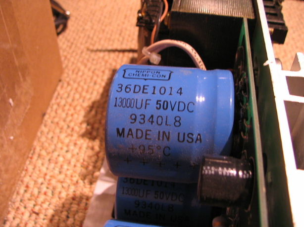
The contacts are heavy guage. The insulators are, like, resin or something, not phenolic board.

IMG_3415_3_1.JPG


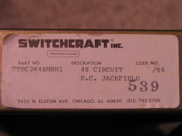
So, again, the JH-416A mixers utilize 5 1U half-width patchbay modules. The factory configuration is 240 points total, 48 points per module. The JH-416B mixers utilize 6 modules for a total of 288 points which could be advantageous if you have a 16+ track tape machine as well as a DAW that's getting tied into the patchfield. The factory modules (which, again, are also made by ADC) are configured as 2 x 24...2 rows of 24 jacks in 2 separate jacks blocks. When I started picking up used ADC patchbays they were all single jack blocks of 2 x 24 jacks...same jack count but squeezed closer together and normalled. I figured that was fine because the first 3 modules normalled anyway on the 416 mixers. Then I started finding the jack blocks with 72 points...3 rows of 24 jacks, 2 rows normalled and the 3rd row doubling the first. When all the wires are removed the first 2 rows are still fully normalled and the 3rd row is independent which is great for the tie lines where non-normalled sources connect. So I have a total of 4 of these 72 point blocks that are in, like, new condition. So I'm thinking of just using the 4 blocks and having 4 modules with a blank for the 5th bay. That would still give me 288 points with the option of adding another 48 points later if needed. The 72 point blocks with 2 normalled rows and a 3rd non-normalled row could actually be really sweet...dense, but practical with room to grow if needed.

And here's another update: I believe I have located a set of the unobtanium JH-416A docs and the owner is kindly allowing me to borrow them and scan them in. I'll keep you posted on that but it would be a real good thing to have a proper set of schematics.
 
Back
Top