sweetbeats
Reel deep thoughts...
I think it’s time to scope the audio path to/from the record/play amp cards. Scope the noise. I’m wondering if you have some HF oscillation going on that you can’t hear but the meters can read.
Last edited:
I think it’s time to scope the audio path to/from the record/play amp cards. Scope the noise. I’m wondering if you have some HF oscillation going on that you can’t hear but the meters can read.
that is a great idea, iv been trying to track down a milivolt meter but i cant seem to find one used locally. Will havr to look into this build a bit more.

I think it’s time to scope the audio path to/from the record/play amp cards. Scope the noise. I’m wondering if you have some HF oscillation going on that you can’t hear but the meters can read.
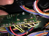
I’m sorry but I can’t follow what you are saying here…0V of what? Tell me what you’re probing by referencing the schematic…there are multiple 0V references. You’re looking for ripple on the power rails (+15V, -15V, etc.), not the ground reference. But this is all moot because clearly your filter PCB assembly is roadkill and you need to fix it. If the traces are hashed cut them out and put in jumper wires, or use the tails of new components as point-to-point jumpers.im seeing 200mVac on the 0v rail and the bias osc. when using a card extender. im having a hard time catching it on the scope.
heres a schem.
View attachment 135614
There is some other mACv hanging around the amplifier but the bias and 0v are the strongest.
Question does the 0v rail = ground, or no?
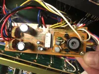
RF from Capstan Motor/Bearings might be an issue. Close proximity to playback head. I had to replace motor/bearings as last maintenance I did on the deck. A VTVM is what I use when tracing anything analog, along with a dual scope if needed. Sorry about the board tracing being in that condition! It's curable thoughI think it’s time to scope the audio path to/from the record/play amp cards. Scope the noise. I’m wondering if you have some HF oscillation going on that you can’t hear but the meters can read.
") Good luck.
Good luck.RF from Capstan Motor/Bearings might be an issue. Close proximity to playback head. I had to replace motor/bearings as last maintenance I did on the deck. A VTVM is what I use when tracing anything analog, along with a dual scope if needed. Sorry about the board tracing being in that condition! It's curable though