Help me fix my 8516

Hello pals, i am once again turning to the forum for knowledge. I really appreciate all the help and knowledge i have gotten so far.

Thank you for your time.


I have been using my 8516 quite heavily in the past two years. It has some issues which have started to get quite out of hand. Im hoping to learn more about electronic repair so i can preform work myself to keep this unit alive.

At this point every function still works, however i am getting unacceptable amounts of noise in my amplifier unit on the outputs. I have what i believe is a 120HZ hum in all channels when armed. The heads also appear to be picking this noise up when im playing back the tape and amplifying it when i record. Another noise i am getting is the skreechy sound of the capstan motor, also in all channels. With the amplifier unplugged the cap motor is nice a quiet.

I have a scope and was hoping to trace the hum to the power supply, however i have very little idea of how to do this properly. i can imagine the aged capacitors contributing to this issue, i dont want to blindly replace them, i would like to learn how to trace this noise properly and learn how to use my scope.

any advice is greatly appreciated.

Best,

mike


Here is a short video of the noise, you can hear the hum in my monitors, its about twice as loud in sync and repro than rec. you can also hear the screeching from the capstan motor, which goes away when i peel the tape from the optical sensor and the motor turn off.
 
405193686_1100010314345175_7460202969270230488_n.jpg404619106_697549885493989_8215903537781629915_n.jpg
404410111_607766314809270_7067260908150667183_n.jpg


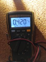
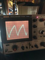
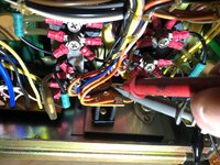
I was tracing this signal from the amplifier regulator card, back to the bridge rectifier. i understand the caps on the regulator card are supposed to filter this ac ripple somewhat. do i have a bad diode?
 
i do now realize that im measuring the "-" leg of the bridge in the photos, i remeasured the positive side and the AC voltage is double.
 
i do now realize that im measuring the "-" leg of the bridge in the photos, i remeasured the positive side and the AC voltage is double.
There’s little value to measuring the AC voltage at either the + or - output of the bridge. There is always ripple there. Scoping could be of some value. I have no idea where you’re probing with the scope in your pic or what your settings are on the scope. So I’m ignoring the pic. I also have no idea where you’re probing with your DMM and measuring AC volts.

Set the DMM to AC volts. Put the common probe to the ground or 0 volt reference for the audio power supply rails at the output of the power supply. Put the positive probe on either the - or + output of the audio power supply. Check both. What is the AC volts measurement at those outputs? There is always substantial ripple at the outputs of the bridge. Most of that should be mitigated by the filter caps. The rest of it is mitigated by the regulator itself in the supply. Trace ripple and noise is shunted by small value caps at the output of most supplies. So the first place to check for ripple is at the output of the power supply. It should be at or very near 0VAC. A couple-three millivolts is okay. But 0 is better.

Your 85-16 is pushing 45 years old. If it was me and the caps were all original, I’d be ordering up new caps and recapping the power supply without a second thought, especially with your hum issue.

<<EDIT>>

I’ve changed over the years from being a fanatic about recapping everything, but this era of Teac/Tascam equipment I particularly like from the late 1970s and 1980s truly is getting to the point where, particularly the power supplies, it almost a given they should just be recapped. And I think the 85-16 was a bit transitional too where some of the caps were more average quality compared to the next wave of products. But even those really should have at least the power supplies recapped. I’m running across more and more circumstances where people are having issues with hum and it’s failed PSU filter caps. The filter caps in the supplies of my late 1960s Ampex 2” machine are all huge computer-grade screw terminal caps. They’re still good. But that’s a different echelon of part than what’s in your 85-16. Recap the supplies.
 
Last edited:
I have replaced all but the three big caps in the PS. They are on order, i pulled the big caps out and measured them, they were still within capacitance spec on my meter.

i measured the output rails, here are my findings.
no more than .2vac on any rail. however there is one rail that has a 25% higher voltage. this was measured at the output from the power supply after all caps and circuits.

Rail / DCV
+15 / 16.68
-15 / -20.11
+15 / 14.68
+12 / 12.17
+24 / 23.41
-8 / 7.95

Problematic?

I Also have found that a most of the main fuses were much larger and have replaced with the ones i had on hand of the correct value. will pick up all new fuses tomorrow.


404539716_304205289282967_2498330331985163189_n.jpg

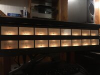
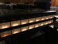
This is my view of the meters at rest with nothing but power plugged into the machine, in sync or repro mode
 
If it was me I would entirely avoid powering the machine up with all systems connected until you get your power supply sorted out. It’s not doing what it’s supposed to do, which is to convert AC line voltage to clean DC power of specific voltages. 0.2VAC on a regulated DC power rail is completely unacceptable. That’s about 100x more than I would expect. And your -15VDC rail…that’s not 25% out of spec…that’s 34%. And regardless, that’s too much. You’ll get different answers from different people on what’s acceptable, and it depends on the circuits being powered, but for this type of system I generally see a range of 14.5-15.5V, and that’s acceptable to me. Even 16V would be okay. Sometimes it’s adjustable. I doubt the 85-16 supplies are adjustable. But both audio rails are running high, the + rail about 11%, the - rail about 34%. And you’ve got unacceptable ripple. The danger in continuing to power all systems is you may have components powered by that -15VDC rail that aren’t rated for 20 or more volts. So you are potentially doing damage to those components. So finish the recap, and re-check. And when you re-check I’d do it with the power supply isolated.

The other thing to consider here is your meter, while a good reputable DMM, its not necessarily designed for audio systems. I say this because if you look at the specifications it’s only rated to measure AC volts reasonably accurately from 45Hz to 1kHz. So that’s great for checking for AC ripple but if there’s something else going on, like a regulator is oscillating at a very high frequency, it’s not likely to pick up on that. Your Hitachi scope can do that though much better. But the Fluke is a great meter, and it is telling you you’ve got way too much AC ripple at the output of your regulated DC supplies. There are multiple filter stages in the supply including the regulator itself. So either the bridge has failed and the ripple is too great for the filters to mitigate, or one or more filter components have failed so they aren’t filtering, or a component, like the regulator for instance, is failing and creating ripple mid-circuit, and the filter components on the output side of the regulator aren’t designed to mitigate that. So I still go back to:

A. Finish the recap
B. Isolate and re-check for ripple at the power supply outputs as well as voltage.

I suspect you’ll still have problems, but the recap is a good thing at this point even if your original caps are measuring “in-spec”. In spec with what? ESR? Capacitance? Just because one or more of those measurements are within tolerance in static testing doesn’t mean a 40-45 year old aluminum electrolytic cap will be able to do its job acceptably under dynamic operation. They’re old. It’s not worth milking them or continuing to hunt for the root cause without replacing them at this point. That’s not a blanket statement for all power supplies…I’m speaking specifically to your machine and situation. It’s what I would do. And then if things look good after the recap, I’d power systems up and re-check for ripple and proper voltage because sometimes a supply is fine under no load, but once you start to load it stuff goes sideways. And if you finish the recap and re-check and it’s still wonky, which is what I suspect you’ll find, it’s time to scope the outputs of the bridge. You should have identical but inverted (relative to each other) truncated AC waveforms. If the mirror image between the two isn’t the same, either in terms of the waveform shape or the amplitude, I’d replace the bridge, re-check the outputs under no load, re-check under load, and if it doesn’t pass either of those tests then scope the output of the regulators. Which is also the next step if things look fine at the outputs of the bridge but the outputs of the supply fail to be in spec with ripple and/or voltage.

Hopefully that’s not confusing. But next step, finish recap, isolate supply, check for AC ripple and DC voltages using your Fluke, if good, load the supply and re-check for ripple and voltages. If either testing stage fails, scope the outputs of the bridge, and report back with images of the scope display for each output of the bridge.
 
Last edited:
I hope you know how helpful it is to have someone like yourself taking the time to write all this out. I really appreciate it.


Hadnt had a chance to update but im pretty much following your advice. The Ps is isolated from the rest of the machine until it runs “normal”.

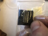
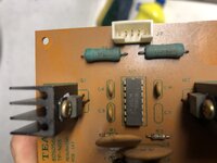
I traced the voltage irregularities on the amp 15+- supplies to the voltage regulator. An old 14 dip dual output unit. I have ordered a new one. Caps are here today. Hoping to have it back together over the weekend. Will report back with pics and finding.

All the best.
 
This is an 85-16 or 85-16B?

I don’t have schematics, layouts, parts lists, etc. for this machine, so my help will be limited unless you have those documents to share. Outside of that the more specifics you can offer the better. What part is the regulator?
 
Hello pals, i am once again turning to the forum for knowledge. I really appreciate all the help and knowledge i have gotten so far.

Thank you for your time.


I have been using my 8516 quite heavily in the past two years. It has some issues which have started to get quite out of hand. Im hoping to learn more about electronic repair so i can preform work myself to keep this unit alive.

At this point every function still works, however i am getting unacceptable amounts of noise in my amplifier unit on the outputs. I have what i believe is a 120HZ hum in all channels when armed. The heads also appear to be picking this noise up when im playing back the tape and amplifying it when i record. Another noise i am getting is the skreechy sound of the capstan motor, also in all channels. With the amplifier unplugged the cap motor is nice a quiet.

I have a scope and was hoping to trace the hum to the power supply, however i have very little idea of how to do this properly. i can imagine the aged capacitors contributing to this issue, i dont want to blindly replace them, i would like to learn how to trace this noise properly and learn how to use my scope.

any advice is greatly appreciated.

Best,

mike
 

Attachments

  • TASCAM 85-16B 16-TRACK 16 CHANNEL MASTER RECORDER REPRODUCER OPERATION MAINTENANCE INC CIRC DI...pdf
    3 MB · Views: 4
Hi, Find attached Maint. Manual. Sweetbeats is on target with supply issues. It's really not that complicated. Transformer, Bridge Diodes, Resistors, Connectors all can be assumed to be solid. Caps are ALWAYS and issue. But of course you have other things to consider. I had to replace the capstan motor as being one of my issues with my 8516b deck. It's been 23 years, but I tried to replace the capstan motor bearings and ended up buying a new capstan motor. I love the deck then and I'm considering of bringing it online again. I used Scotch 250 / 250nw/meter / overbiased 3-4db @ 10khz (just enough to keep a 1 db lift @ 12khz).
 
That’s the same one I have…only partial schematic excerpts…no layouts, only partial parts lists…
 
I have the “A” model. Orange legs.

I own a hard copy of the 85-16b manual. Its mildly useful for PS schematics. The pinouts are similar but the circuit is redesigned. Wrkrbee has a proper manual for me but im having a hard time communicating with him.

I got the new chip in the mail and replaced it. Nice and even +\-15 on the amp rail now.

I replaced all the fuses with the proper amp ratings.

I still have ac lingering on all rails and measuring with my fluke (which i dont really trust) im seeing 0.08vac.

I breifly connected the amp to see if the noise was still present. Its gone, well gone is the 60hz hum and has now been replaced by a high frequency buzz hum. Its coming from every channel in sync and repro mode. The vu meters on the machine now also read around 0db at idle, with or without tape.

Im gonna scope a bit and post some photos.

I know that i will need to realign the whole machine once i solve these issues.
 
Ah okay…you’ve got a “flamingo”. :D

What part is the regulator?

Why don’t you trust the Fluke DMM? That’s a good meter.

Good job identifying the regulator IC as at least a significant part of the problem.

You might still have noise because 0.08V of AC ripple at the output of a regulated DC supply is too much. Did you put the new primary filter caps in yet?

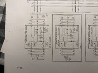
Do post pics of what you see on the scope, but also maybe pics of how you have the controls set, and if you can post a pic of the 85-16B power supply schematic that would possibly help too. You could reference the schematic as to where you are probing even if part references are different or there are differences in the circuit.
 
Mc1468l was the original voltage reg, i replaced it with a Philips equivalent.

72591294654__7C37B186-9D01-4C5C-8B89-809E1FDCF1B4.jpeg
Heres a little pic of the board that regulates the 15v power
IMG_2609.jpeg

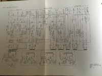
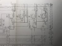
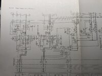
Heres the B version schematics.
The main 3 caps are the same in mine.
I managed to find a 35v 33000uf cap.
However i cant locate the other two. 50v 8200uf, any idea where i can find a suitable replacement.


Im weary of the fluke when measuring delicate electronics for AC, it seems to have ghost readings, i generally trust it for automotive repair which is what i do.

IMG_2598.jpeg
IMG_2597.jpeg
IMG_2596.jpeg
 
The very poor HF response of digital multimeters is not at all well known. Even those said to be "true rms" are really only fit for 'power' frequencies (maybe up to 400Hz if you are working on a WWll bomber!) I am lucky to own an old Fluke 83 which does cover the audio spectrum (I must check it though!)

However, you can build a very useful analogue AC meter with a response up to at least 30kHz using a VU meter movement, an OP amp* and 4 OA91 diodes. Buy the biggest and best VU meter (or a 0-10, 0-3 conventional meter but then you have to 'do the dBs') you can afford. The meter can be calibrated at 100Hz against a digital and checked through the audio band with frequencies generated in a DAW. Audacity can do that.

*Or discrete transistors. Google for "J Lindsay Hood test equipment". (I shall do so now) For level adjustment and tape alignment an analogue meter is often easier and quicker to use than a flickering digital.

https://www.worldradiohistory.com/UK/Wireless-World/70s/Wireless-World-1970-12.pdf Not found JLH so far but that shows the principle. You only really need the meter drive part for line levels. The whole thing can be built around a TL072.
Dave.
 
Last edited:
that is a great idea, iv been trying to track down a milivolt meter but i cant seem to find one used locally. Will havr to look into this build a bit more.
 
Back
Top