Making the Boards
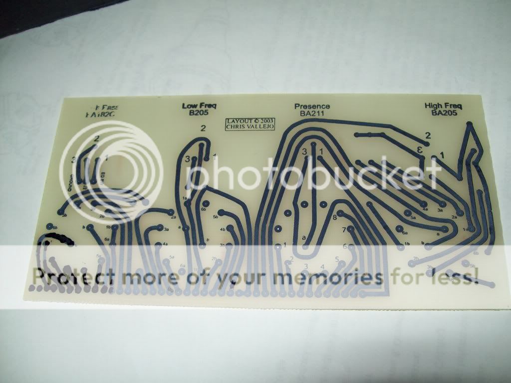
As I said, I used Linear-Recording's 'all in one' design.
It is an accurate copy, other than the power smoothing electrolytic capacitors are 10x what Neve used. Not a problem.
I used 'Press-n-Peel PCB Transfer Film' that costs about $10AUS per A4 sheet.
Cut the PCB with a hacksaw to size.
You print the design using a laser printer with the toner turned to maximum.
Clean the PCB board with steel wool and wash thoroughly. Do not touch the surface afterwards(oils).
You iron the design on with a dry iron set near max. No steam or water.
Put baking paper over the top and iron onto this.
Large boards need more heat than small boards. Takes about 3 minutes. Move the iron around slowly and make sure you spend 60-70% of the time near the edges (they cool quicker and need more heat).
After 3 minutes carefully lift up one edge. If the plastic sheet has totally stuck to the pcb or the design near the edge stops you carefully lifting the plastic, then you are done. If not, lower carefully down and do another minute and retest.
You then quench under a cold tap and carefully lift the plastic off.
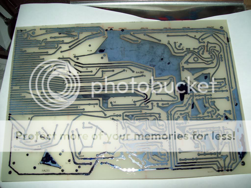
You should now have blue lines:
You use a special pen to touch up the design. This is black in the photo.
You could use photoresist boards, but this is more expensive and I could not get photoresist pcb boards big enough for the Linear-Recording 'all in one'.
Visually check the board for 'shorts' and use a sharp point to scratch between any connections that should not be there.
The best etchant is Ferric Chloride. Put a mix into a flat pan and rock from side to side. Takes about an hour for this large board.
If you think that it is going too slow, pour out the old solution and add new.
Don't add new to old as you are diluting the new...
It is best to leave as is until you are going to start populating the board to stop copper corrosion and soldering problems.
When ready, clean the blue film off using steel wool in a sink of water.
You can try running solder along the tracks, but looks aweful and may cause other problems.
Now check for shorts between every board connection. Use a sharp point to scratch between any. With a multimeter set to 'Ohms' and set to make a sound if there is a 'short', move the points of the probes across the boards where they will connect together. None of these can be connected. THIS IS REALLY YOUR ONLY CHANCE TO FIND THEM!!!!!!
Also go around the board and check copper runs are not connected to any others (unless by a roundabout route - they are actually part of the same run).
Also check that the ends of each copper run are connected (ie there IS a short). Check all branches of the run are connected. You are looking for cracks or discontinuities. Solder over any found.
Try and be systematic and check all of the board. Problems are easier to find now than when you put in components.
Till next time - Garry
")
")