N
Neve1073lover
Inset French Saying Here
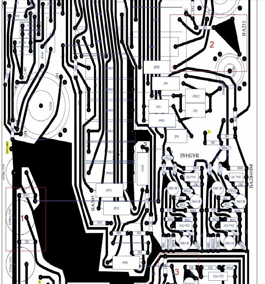
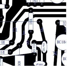
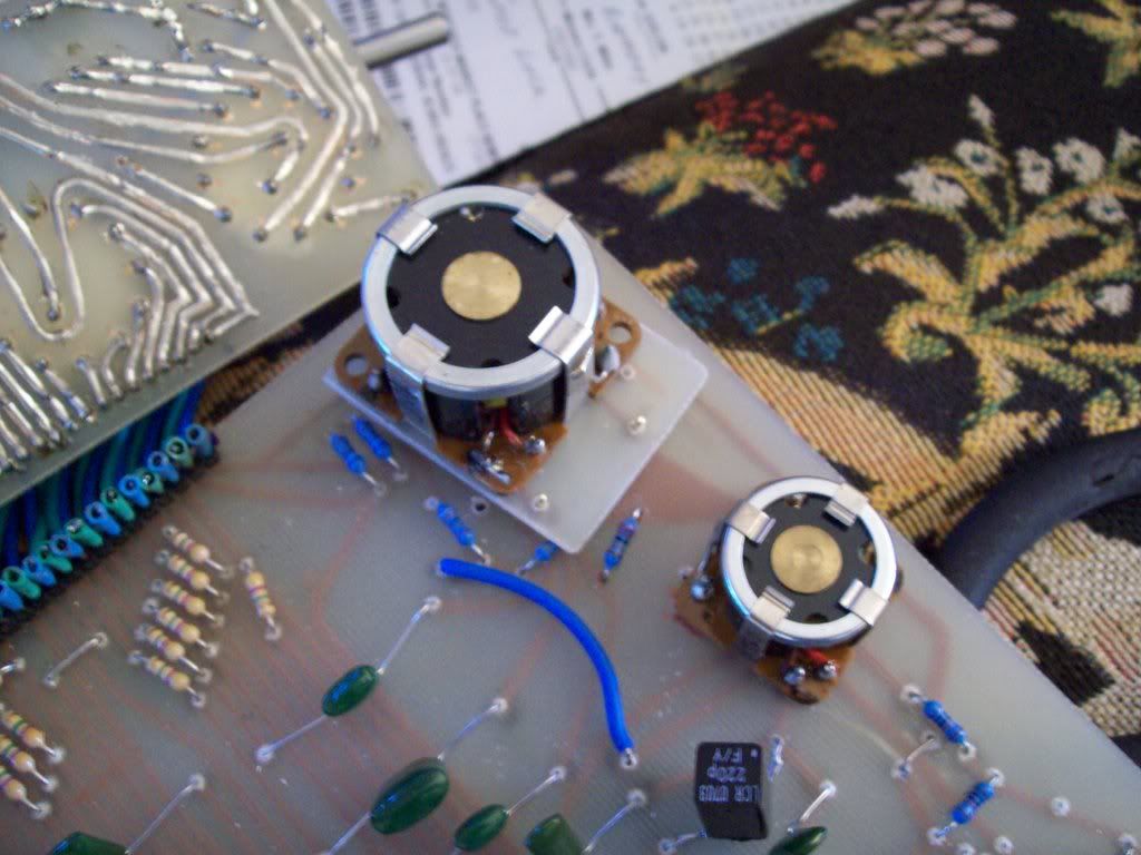
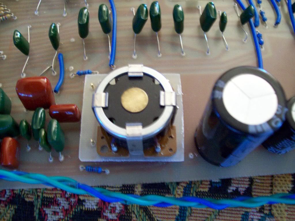
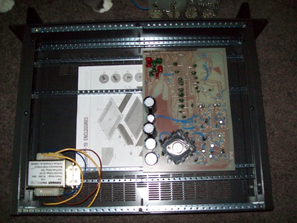
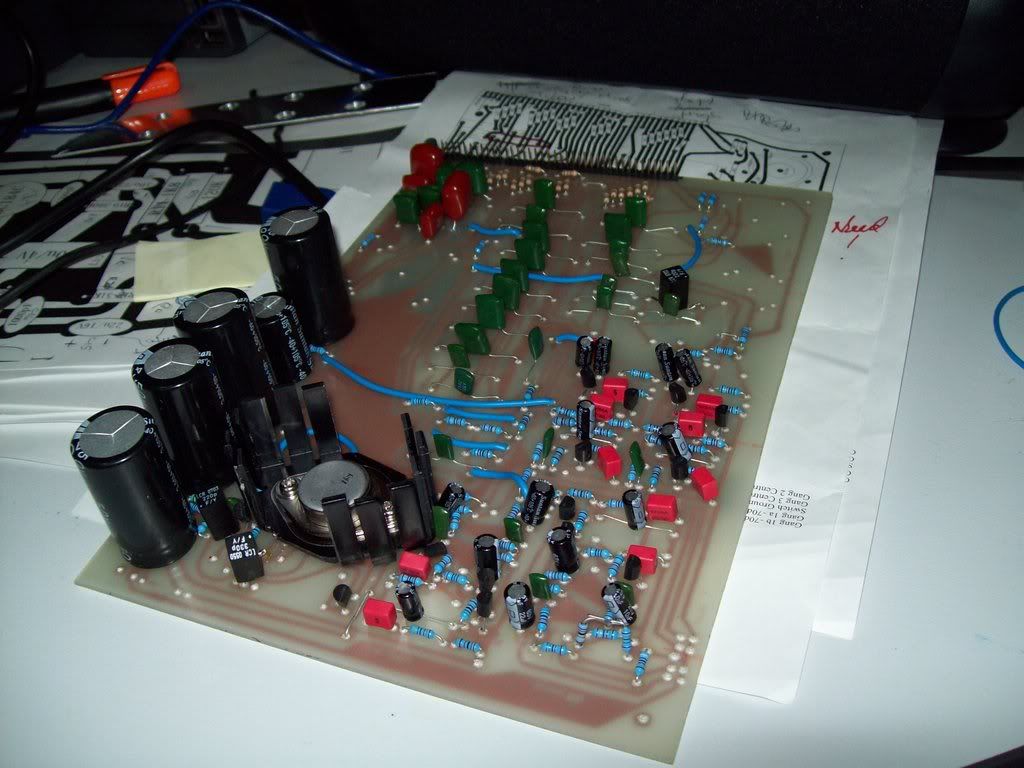
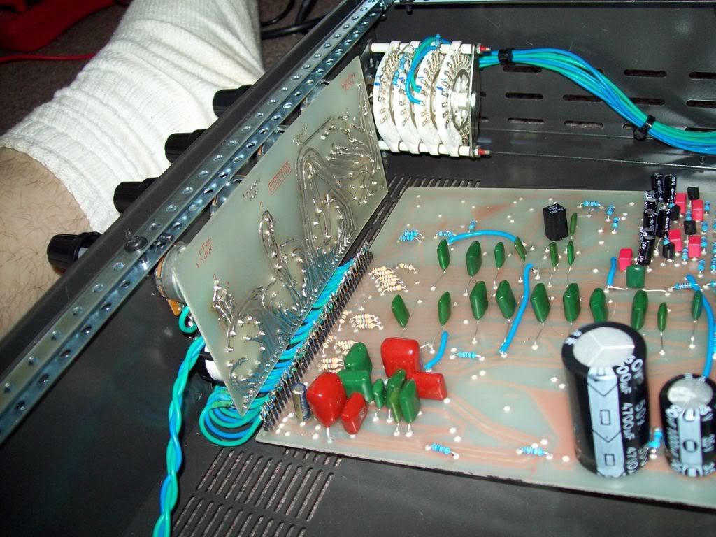
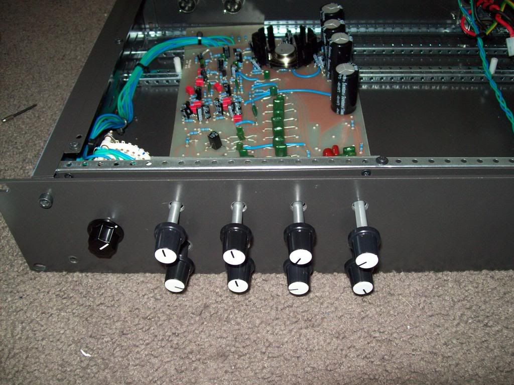
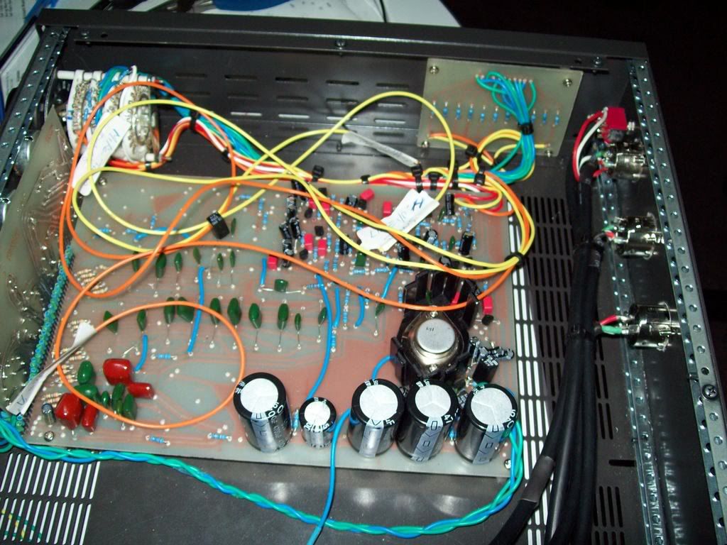
The Main Board
I used greencaps mainly becuase I could not get the correct polyester caps.
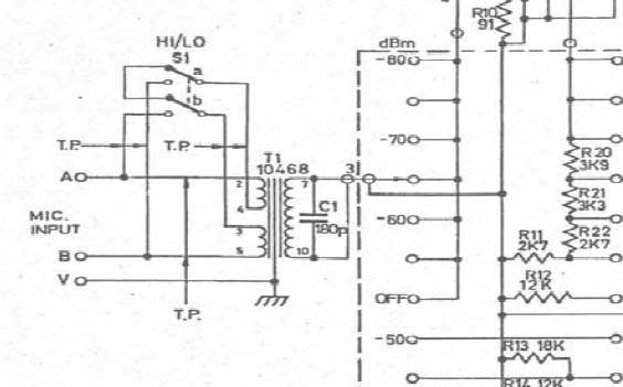
I did not use any ceramic capacitors on the main board as they are shit. I use one only on an input transformer as it was the only way to get the correct value.
Try and use greencap or mylar as a minimum.
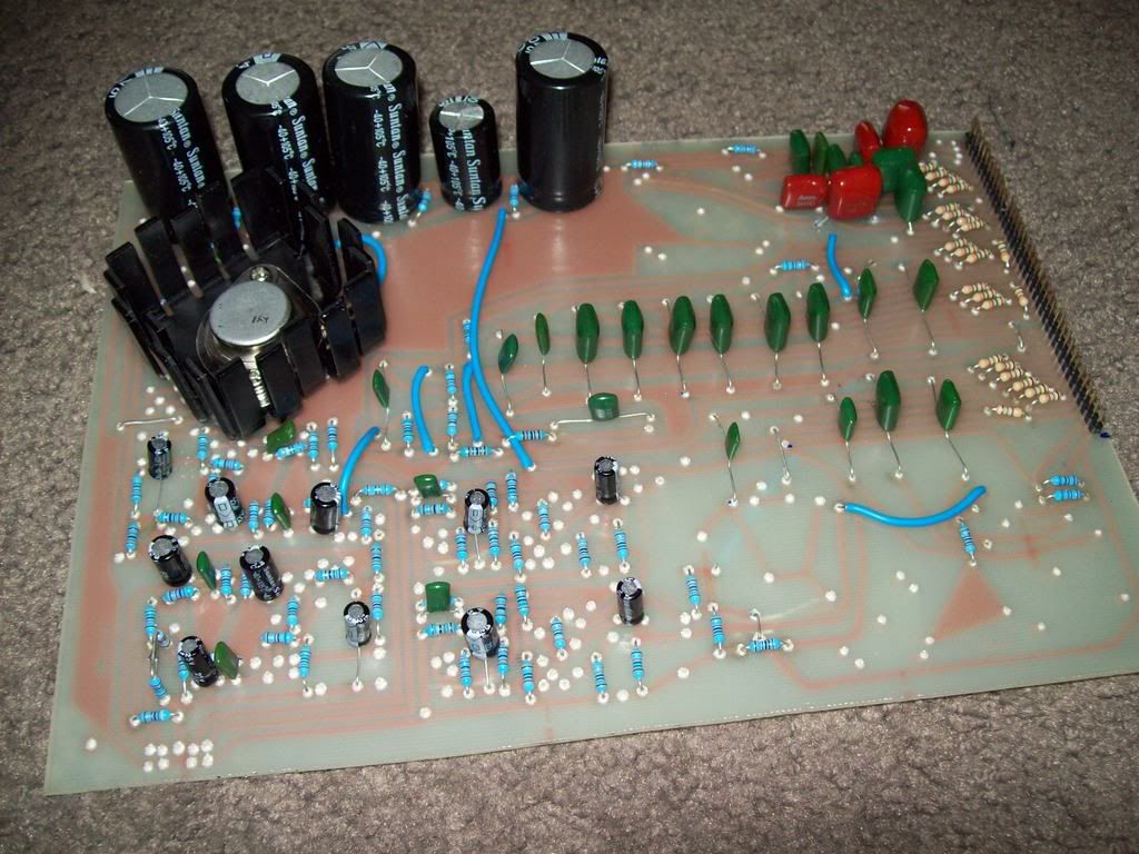
Most small electrolytics were either 16V or 25V. Use either.
There are some electrolytic values I could not get. 80uF 25V was one of them.
Get a 33uF and a 47uF both 25V and wire them in parallel (+ to + , and - to -). Caps add together in parallel.
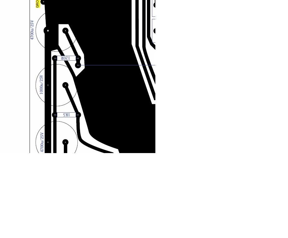
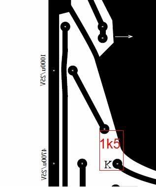
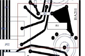
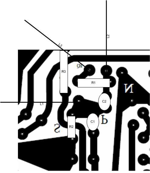
There are 3 errors on Linear-Recordings 'Stuffed' pdf. I will show them in my next post.
I used greencaps mainly becuase I could not get the correct polyester caps.
I did not use any ceramic capacitors on the main board as they are shit. I use one only on an input transformer as it was the only way to get the correct value.
Try and use greencap or mylar as a minimum.
Most small electrolytics were either 16V or 25V. Use either.
There are some electrolytic values I could not get. 80uF 25V was one of them.
Get a 33uF and a 47uF both 25V and wire them in parallel (+ to + , and - to -). Caps add together in parallel.
There are 3 errors on Linear-Recordings 'Stuffed' pdf. I will show them in my next post.