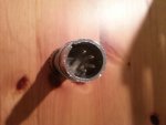
Cannon XLR 4 Pin Question

Hey guys,

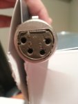
I recently acquired an old dynamic microphone, there are no brand markings on it but appears to be from the 60's or possibly 50's. The output of the mic is fitted with a male Cannon XLR 4 11-C connector. I received this mic with it's original cable which has the female 4 pin on one end and a standard male 3 pin xlr on the other. When I plugged in the mic to my console I got nothing but buzz so I checked the ends of the cable connectors and sure enough some wires were loose on the male 3 pin. As of now i'm trying to figure out which wires to solder back to their respective pins since there are 4 separate wires including the shielding. Was wondering if somebody with some expertise could share some info with me. I'm really wanting to hear how this thing sounds! Thanks:)
 
A photo would be useful.

Two reasons for a 4 pole conn'
1) The mic has a switch for a remote function e.g. TX/RX switch.

2) The mic is dual impedance. Usually low, nominal 600Ohms and high, 50k but you won't measure these resistances on a meter because that just measures DC, not "AC" impedance.

And last of all, for the bloody UMPTEENTH time!! All of you!! BUY A BLOODY DIGITAL MULTIMETER!!

You really can't learn JACK about this stuff without one.

Err? DON'T go poking around measuring continuity on an old ribbon mic!

Dave.
 
+1 to Ecc83. Can't do much without a meter. Even a $5 market one with continuity test is a really handy tool


Do I understand correctly : the mic has a four pin connector, but the cable adapts 4 pin to 3 pin for standard consoles/preamps etc?

I'm thinking the same as ECC.
Either there's a switch using the extra conductor, an extra different impedance output, or it's just a spare pin n/c.

If this is the case, there's a good chance you don't have a loose or broken wire. It may just no N/C on purpose.
This is common enough in older mics.
 
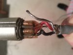
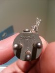
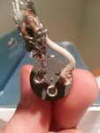
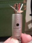
Thanks guys for your responses. Yes I have a multimeter but i'm not really sure how to use one for this application, sorrily. I would really appreciate if you guys could help me learn how to measure each conductor to decipher which i need to be solder as my - + and ground on the XLR pins. I'm going to post some clear pictures within the next couple minutes. @ Steenamaroo yes you understood correctly the mic has a four pin connector, but the cable adapts 4 pin to 3 pin. The microphone DOES NOT have an external switch.
 
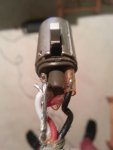
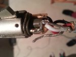
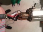
Male XLR 3 Pin (White pin 1, Shielding/Red/Black pin 2)

I cut the 3 pin connector from the cable because i would like to get clean solder connections for obvious reasons.

20140221_223030.jpg

20140221_222612.jpg

20140221_222940.jpg
 
Clearly the uninsulated wire is the shield/ground, pin 1 at both ends. The logical pinout arrangements would be:

1 = ground
2 = high impedance
3 = low impedance hot
4 = low impedance cold

or

1 = ground
2 = low impedance hot
3 = low impedance cold
4 = high impedance

Because the white is already going from pin 2 to pin 2 I would bet that pin 3 goes to pin 3 and that pin 4 is high impedance. Use test leads with alligator clips to reconnect them, with the red wire to pin 3, and see if that works. Of course the cable could have been wired incorrectly so you never know.
 
Although I said you can't measure the actual impedances with a DC meter it will sort the high Z connections from the low.

High Z will read a few kOhms, but nowhere near 50k. Low Z will be very low, 150 Ohms or lower. If it is a very old mic it could be a 30Ohm model in which case the DC R will only be a few Ohms (I have 15! Ohms Gelloso lavalier mic)

The High Z coil might or might not have one end tied to the casing/shield. Low Z might read to case if it uses a centre tapped output transformer but this is unlikely and in any case the windings will read very nearly the same about "earth".

Dave.
 
A photo would be useful.

Two reasons for a 4 pole conn'
1) The mic has a switch for a remote function e.g. TX/RX switch.

2) The mic is dual impedance. Usually low, nominal 600Ohms and high, 50k but you won't measure these resistances on a meter because that just measures DC, not "AC" impedance.

And last of all, for the bloody UMPTEENTH time!! All of you!! BUY A BLOODY DIGITAL MULTIMETER!!

You really can't learn JACK about this stuff without one.

Err? DON'T go poking around measuring continuity on an old ribbon mic!

Dave.

I think there's at least one more possibility. I seem to recall having a bunch of microphones that used a 4-pin connector in which the fourth pin was DC power (9V, IIRC). We originally used cables that were rewired to have a standard XLR and a 9V battery holder down at the plug end, but at some point, I built a power supply brick. Ask me how long a 10,000 uF capacitor will power three electret capsules....
 
Back
Top