February DIY Challenge!

  • Thread starter Thread starter mshilarious
  • Start date Start date
The input transistor pairs in front of TL071 would be to improve the noise performance of the front-end, but that only matters in a mic-amp application.

Yes indeed. Unnecessary and unwanted for line level input, which is why their stock line inputs (which are just padded down feeding the same transistors) are undesirable.

You can bypass the opamp, but by that token, you can also run the AD chip unbalanced by referencing its inverting input to its MOD pin.

Thanks for pointing that out. I didn't even consider that route.

I just don't think you'll get the same low distortion out of a single FET vs. an opamp, and I don't think you'll gain much with 1" of a balanced circuit when the 10' before it is unbalanced.

You are right about distortion, although the single FET will be Class-A, so maybe I'll like that higher distortion. Really it is just expediency, since I have a pile of 2SK170BL. I was thinking that the AD chip wanted to see a balanced signal, and what was the shortest signal path to give it that.

Personally, I strive to make all connections balanced, but that is somewhat of a necessity in the EMI hell that is my house. Transformers are perfectly happy doing either one, so if you prefer unbalanced, maybe you just don't like the sound of that transformer :confused:

I record sometimes in a studio that is EMI danger zone, and the balanced outs come in handy. I would say I use the unbalanced to balanced 60% to 40% of the time, so I do actually like both very much and find the contrast useful.

Does Black Lion want $300 to swap out a few opamps? Ouch.

I won't say anything negative about my fellow Chicagoan, he has shared information and been super helpful to me in the past. Although, that does seem excess for the described scope of the mod.
 
You are right about distortion, although the single FET will be Class-A, so maybe I'll like that higher distortion. Really it is just expediency, since I have a pile of 2SK170BL.

As Bruno Putzeys is fond of arguing, if you design distortion into a circuit that is not per se an effects box, you ought to make it switchable. Desirable FET distortion is typically asymmetrical soft clipping that throws off lots of second-order. The easiest bias arrangement for this box would be to strap the drain and source to +/-15V across resistors, and ground reference the pin. But if you stuck a pot from +/-15V with its wiper to gate, you can create any bias you want for many different flavors of distortion.


I record sometimes in a studio that is EMI danger zone, and the balanced outs come in handy. I would say I use the unbalanced to balanced 60% to 40% of the time, so I do actually like both very much and find the contrast useful.

Again here, you seem to have separate issue of the sound of the transformer vs. the configuration of the output. What about an impedance-balanced output that is switchable with the output transformer? A DPDT switch, a TRS jack, and your output becomes selectable with the switch and the type of plug inserted.


I won't say anything negative about my fellow Chicagoan, he has shared information and been super helpful to me in the past. Although, that does seem excess for the described scope of the mod.

I don't have much negative to say either, just that price seemed out of line given the prices of his more extensive mods. Maybe that's intentional if he doesn't really want to work on that box, but still gets pestered by people about it (I mean, you can pick one up for less than $200 now).

The reason may be that he does a lot more stuff to the box that he doesn't say. I'm not real fond of that approach--I mean, open up the box and you can see anyway. Analog audio electronics are no big secret in 2009. The guys (and I am not saying he is one of them) who scrub labels off ICs--or even worse, epoxy entire circuits--really annoy me. Especially if they use any open source software! :p
 
The Loop Switcher I mentioned in the post above is just that impedance converter in front of a DPDT stomp switch, for when I want to bypass all the pedals and go straight to the amp. Instantly eliminates any noise contributed by daisy chained, buffered pedals.
Hmm... I guess I'm going to have to look into that more now, then. My goal is to make something like this:
http://guitars.musiciansfriend.com/...ofessional-Pedal-Management-System?sku=542022
I'm not going to have all that power supply stuff (just an outlet strip), but I like how they have the grid thing for cable management. What I would like to do is attach input and output jacks to the side of the box, preferably with a signal buffer on the output, and then have a bunch of footswitches on the bottom row for bypass individual effects and a master bypass. I don't have any idea how to go about the switches, though, or where to get the buffer thing...
 
As Bruno Putzeys is fond of arguing, if you design distortion into a circuit that is not per se an effects box, you ought to make it switchable. Desirable FET distortion is typically asymmetrical soft clipping that throws off lots of second-order. The easiest bias arrangement for this box would be to strap the drain and source to +/-15V across resistors, and ground reference the pin. But if you stuck a pot from +/-15V with its wiper to gate, you can create any bias you want for many different flavors of distortion.

Now that's an intriguing idea. IIRC, the Peesonus MP20 included some scheme like that, with what was described by one designer as "a dirty biased FET" to manipulate the distortion spectra.

When we talk about the higher inherent distortion of the single FET vs. the IC opamp, we may not be talking about anything very audible or perhaps only audible on sudden transients. Clipping is such a gross example, we don't usually design for it rather just to avoid or minimize it.

Simply put, I don't expect any drastic difference in distortion at all between the devices operated in their normal, linear range. There may be other parameters better able to describe the differences I hear between a FET-input Opamp and a single FET gain/buffer stage. Slew Rate may be one, although it has been abused so much by aggrandizing audiophools I don't like to go there. :p

Anyway, thanks for carrying on the discussion with me. I didn't want to bring this idea up over at Prodiy-pro.com/diy because I could anticipate certain responses there.


Again here, you seem to have separate issue of the sound of the transformer vs. the configuration of the output. What about an impedance-balanced output that is switchable with the output transformer? A DPDT switch, a TRS jack, and your output becomes selectable with the switch and the type of plug inserted.

Separate issues (applications), but in either case I'm happy to use the transformers. Given that, it's not worth my time to impedance balance or electronically outputs in addition to the current arrangement. I'll sacrifice the luxury of choice when balanced is necessary due to the environment. After all, the difference is barely perceivable.

However, when layering certain instruments in a mix it does help to use the contrast between the transformer sound (the gestalt of slight phase shift, higher distortion, and unique "core material" timbre), and the unbalanced sound to keep instruments distinct in the mix. I just try to think about how I want it to sit in the mix, and the best signal path from mic to converter to achieve that. Sometimes that path include a bunch of transformers and sometimes none.

In the grand scheme being able to remove one of those transformers may not make a big enough difference to warrant the effort. I like to think it does.
 
resolder my alligator clip leads :D

try out some different capacitors in my ACM-900

somehow get in touch with ART support so they can sell me a replacement main board for my Digital MPA that I hosed on my last DIY project :D
#1 DONE! (they were really bad - weird) :D
#2 - not sure what I'm going to do here - there are only three caps, and they're all electrolytic with either high capacitance or high voltage ratings. I got some dipped tantalum. There is a 1uF 300 volt one, and I got a massive poly to replace it, but it's too big to fit. I hope to reduce hiss a little, but may just leave it alone in the end.
#3 DONE! In that I got in touch with them - but they don't sell new boards. So I guess I need to change this item to "trace and repair the damage I did to Digital MPA...
 
#2 - not sure what I'm going to do here - there are only three caps, and they're all electrolytic with either high capacitance or high voltage ratings. I got some dipped tantalum. There is a 1uF 300 volt one, and I got a massive poly to replace it, but it's too big to fit. I hope to reduce hiss a little, but may just leave it alone in the end.

Ah, the tube ribbon. A strange concept in a mic if I have ever seen one :D Not that I am averse to strange concepts in tube mics . . . :o

You generally don't use tantalums in the audio path unless there is no other choice. That would only be the case if there was not room for an electro. The distortion of a tant cap is an order of magnitude higher than an electro (and the electro the same to a poly). Given that there is little room for sexy tube-stage coupling caps inside a mic with two transformers and a tube, I'd stick with a higher-quality electro.

I doubt swapping the caps will have any effect on the mic's self-noise at all. The sources of noise in that circuit are primarily the resistance of the ribbon transformer, stepped up by the secondary and multiplied by the current noise of the tube (probably not a small figure). Secondarily, there is the voltage noise of the tube. The caps would only be implicated if they were undersized for the job they needed to do (and that they were filter caps, of course). Capacitor distortion has little to no effect on power supply filtration--that I have been able to measure anyway.

To pull off a successful low-noise ribbon system, you need a ribbon transformer with a very low primary DCR, followed by a low-noise amplifier (especially very low current noise). If the transformer ratio is high, you can successfully avoid most other noise sources. The main reason to do an active ribbon design is to enable to use of a high turns ratio transformer--that gets you above the voltage noise of the buffer amp, which solves the problem of the higher output impedance of the "overwound" transformer.

But if you use an inappropriate ribbon transformer and stick it into a noisy tube, no capacitor can help you . . .
 
Thanks - actually, the noisest part may be the tube I put in it. I let it run for a couple of days, and it was much better. I suppose I can check off #2 also :D -- (which leaves me with a bunch of trace testing to do :( )
 
Foward motion on #1

Got out of work early, the weather was nice so out came the saw and drill. It's just "tacked" together with screws for now and still needs alot of work but it's getting closer for paint and stain.
 

Attachments

  • P1010152MOD.webp
    P1010152MOD.webp
    39.2 KB · Views: 149
  • P1010154MOD.webp
    P1010154MOD.webp
    40.2 KB · Views: 152
The black electrolytic cap seems to just be a DC blocking cap between the output pin of the tube and the red wire to the output transformer (whose other end is grounded). I would expect that a smaller value (but similarly high voltage) cap would work reasonably for such a purpose. Do you concur, Jon?
 
The black electrolytic cap seems to just be a DC blocking cap. I would expect a smaller value (but similarly high voltage) cap to work reasonably for such a purpose. Do you concur, Jon?

I assume that's the 1uF cap? I haven't seen a schematic. I don't think a much smaller cap is a great idea because the output transformer probably isn't real high impedance, and that depends on the preamp too. I mean sure, maybe 0.47uF, maybe 0.22uF, but I don't know how small you'd need to get to fit a poly in there.

The other two I would guess are a filter cap on the plate supply and a bypass cap on the cathode . . . dunno really though.
 
Got out of work early, the weather was nice so out came the saw and drill. It's just "tacked" together with screws for now and still needs alot of work but it's getting closer for paint and stain.

Beautiful!!!

That's seriously impressive.

All I have is a simple little Kalimba that I'm working on at the moment. Can I post that?
 
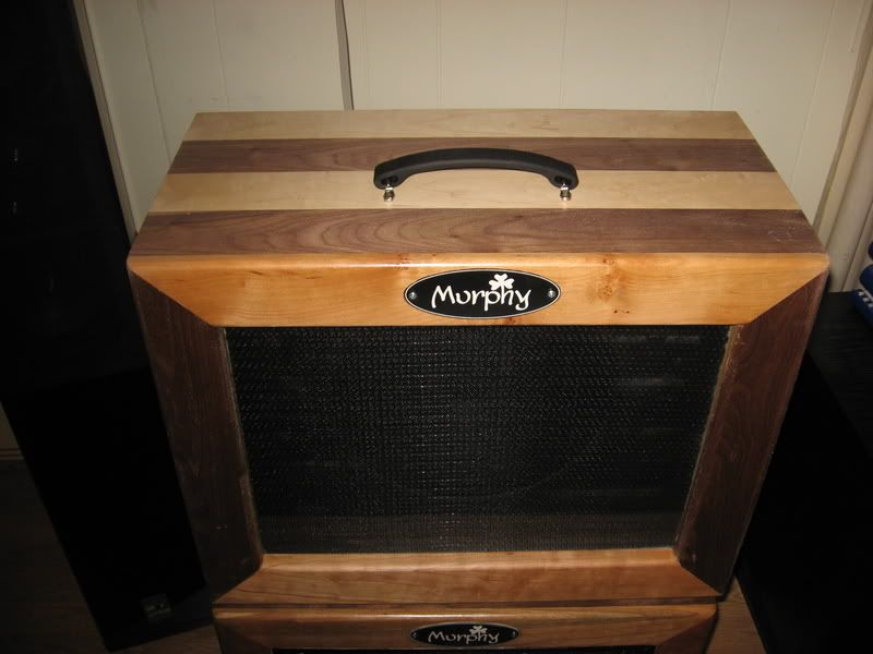
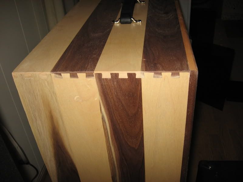
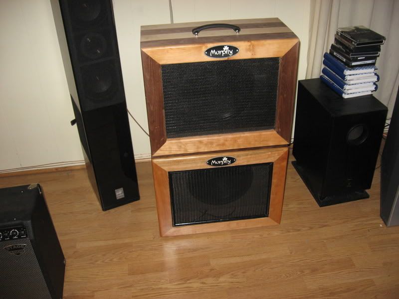
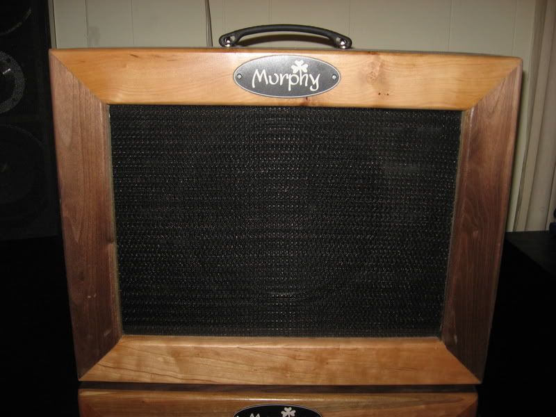
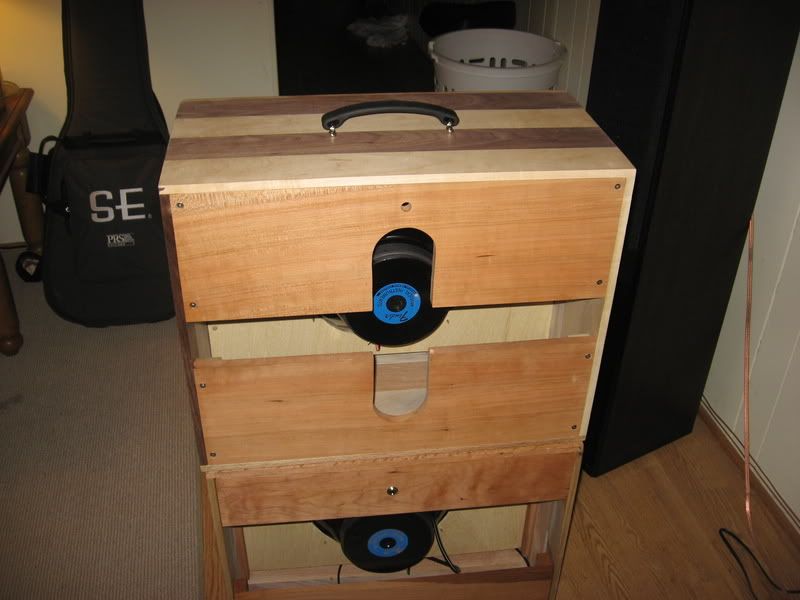
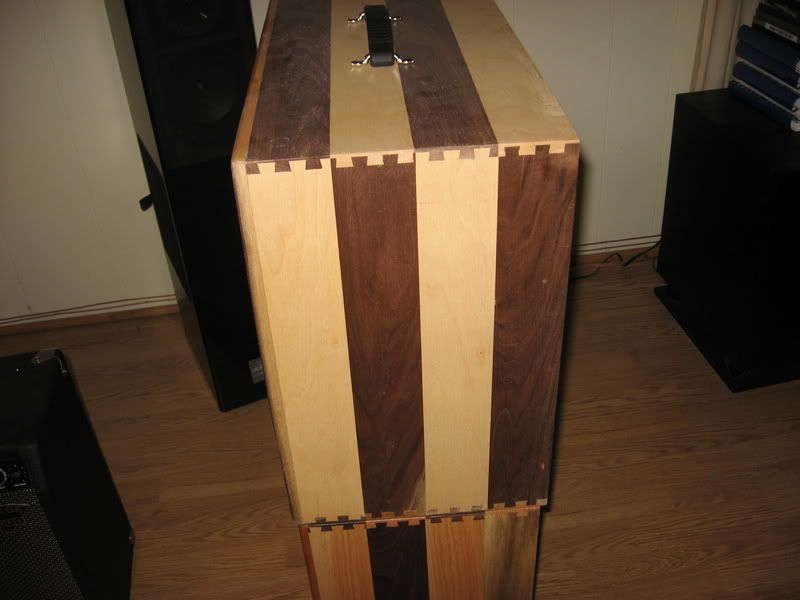
I just finished Two 1-12 extention cabinets. I've been threatening to do it forever and finally got off my duff.

Walnut & Oak, I used Cherry on the backs of both and cherry on one front and cherry/walnut on the other. One is "classic openback" the other is slightly different but still an open back.

I guess I'm not totally finished, I still need to wire the second on, but that'll just take a few minutes.

Plates are from amplates.com, the rest is misc. stuff from parts express and MF.com


IMG_0262.jpg

IMG_0263.jpg

IMG_0264.jpg

IMG_0265.jpg

IMG_0266.jpg

IMG_0267.jpg
 
Wow Creamyapples1! Great looking cab... Congratulations!
 
Come on, guys... Let´s see the pics! :D
I'll put some up later today, but probably in a separate thread so I can recruit some help later :) This pedal board is turning out to be a lot more complicated than I anticipated...
 
I'll put some up later today, but probably in a separate thread so I can recruit some help later :) This pedal board is turning out to be a lot more complicated than I anticipated...

Pedalboards can be a very quirky beast, just don't make the same mistake I made. I figured out EXACTLY what I wanted, spent all sorts of time making the board then decided I didn't want to use 4 or 5 of the pedals and got rid of two of the amps whose footswitches were taken into consideration when making the board in the first place. Now I'm stuck with this big damn thing and only need about half of it. Go me!
 
I've been thinking about dropping Bo Hansen's little FET impedance converter into my guitars. I have one in a stomp box FX-loop switcher and really like it.

http://web.telia.com/~u31617586/#simple%20FET%20impedance%20converter

Any interest in sharing your design? I totally understand if you want to keep it under your hat. :cool:

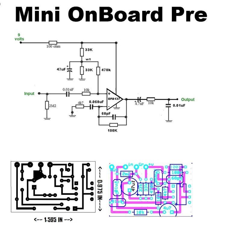
Sure...I don"t mind shareing , It is actually a very simple curcuit , Just a single fet opamp with a pretty high gain...

Actgit-pre-pcb.jpg


It has a Gain of about 22x or 26db but if you want to build it you can replace the 100k gain set resistor with a Pot or trim pot to get adjustable gain....

You connect the TRS Input jack the standard way like with most pedals with battery ground connecting to Ring and curcuit ground connected to Sleeve....


Cheers
 
Pedalboards can be a very quirky beast, just don't make the same mistake I made. I figured out EXACTLY what I wanted, spent all sorts of time making the board then decided I didn't want to use 4 or 5 of the pedals and got rid of two of the amps whose footswitches were taken into consideration when making the board in the first place. Now I'm stuck with this big damn thing and only need about half of it. Go me!
I'm trying to make mine as adaptable and future-proof as possible, so it's a little bigger than I need right now, but I can easily see myself having a couple more pedals if I had the money. It's a real pain in the butt to make, but it's going to be worth it in the end.
 
Sure...I don"t mind shareing , It is actually a very simple curcuit , Just a single fet opamp with a pretty high gain...

Actgit-pre-pcb.jpg

I don't get the 10K output resistor. Together with the 0.01uF shunt cap, it's like having your tone control on full cut all the time. I would go with something more like 150.
 
Back
Top