weird waveforms

this is cool to play around with to see what effects it.
more pictures to reaffirm what everyone's already been saying (plus, because I'm bored and I found the before and after pics to look cool :D )
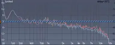
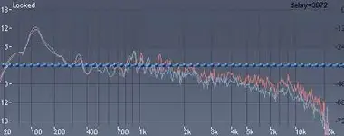
Just a 20Hz cut, 6dB/oct cut and it effects it dramatically in the lows...and effectively fixing the offset.
 

Attachments

  • Before.jpg
    Before.jpg
    8.1 KB · Views: 20
  • After.jpg
    After.jpg
    7.7 KB · Views: 21
Last edited:
Massive Master said:
(chiming in late)

Boy - Just goes to show you not to trust your dislpay... I opened that file again - Waveform *looks* totally normal in WL4. Nothing like Tom's in SF. And analysis shows around 12dB offset. Freaky. But still, as mentioned, it seems to be whacked in the subsonic space for some reason...

In WL5 it looks normal at 500ms ruler resolution, but when you flip the next zoom level to 200ms it looks appropriately whacked. Seems like a bug; I might bring it up on the cubase.net forum :confused: I'd guess that at zoomed-out resolution, the program makes assumptions about negative peaks from positive values, essentially generating a symmetrical waveform.
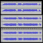
Also although WL analysis shows the 12dB DC offset, the DC offset tool does not work here since the waveform is essentially more rectified than offset. It's necessary to use a low-pass filter. 6dB/octave is insufficient; I'd use 18dB/octave.
 
Thanks for all of the advice everyone, I'm going to work on fixing it when I get home from work.

I should have noted at the beginning of this that I have a very unconventional setup for my studio (if you can call it one). I Recorded the drums to a digital 8 track and bounced the wavs to vegas. Then for guitars and bass I ran a SM57 into the 8 track and then ran the line out of the 8 track into the line in on my PC and recorded straight into Vegas. I think this probably has something to do with the problem, and I've got a new pre-amp for my next batch of recordings.
 
more pics
top pic is the original, middle pic is with a 1Hz high pass filter, and the bottom a 10Hz one.
I found it interesting that applying a 1Hz high pass filter almost entirely fixed the problem. There is still a slight dip where the cursor is and near the end (during the quiet section)....but then a 10Hz filter tweaks it a bit better.
 

Attachments

  • Take2.jpg
    Take2.jpg
    31.8 KB · Views: 52
tarnationsauce2 said:
Maybe it don't know exactly how to interperet "0"Hz.

I'm not sure I know how to interpret 0 Hz either. What are the overtones produced by a frequency of 0 Hz? Theoretically none I would assume, in practical applications are there some produced for some arcane reason?

In Benny's experiment theoretically a sharp 1 Hz high pass should do the trick. But again in practice I would guess that it's next to impossible to create a filter with a slope that steep, which is why 10Hz worked better. When removing DC offsets I've used 20Hz assuming that there's nothing we want below those freqs anyway.

A very interesting thread!
 
bennychico11 said:
more pics
top pic is the original, middle pic is with a 1Hz high pass filter, and the bottom a 10Hz one.
I found it interesting that applying a 1Hz high pass filter almost entirely fixed the problem. There is still a slight dip where the cursor is and near the end (during the quiet section)....but then a 10Hz filter tweaks it a bit better.

Yeah, I suspect the DC signal changed levels during the tune, that's why a higher cut is required.

Yannow, I think it was last week that we discussed whether or not low cuts were useful as a general practice on tracks that don't have fundamentals in the range of the cut . . . again I say yes!
 
mshilarious said:
Yannow, I think it was last week that we discussed whether or not low cuts were useful as a general practice on tracks that don't have fundamentals in the range of the cut . . . again I say yes!

I say yes too, and in some cases a low pass to remove high freqs. Not because they aren't part of the original source, but it's a question of what they are contributing to the mix?
 
masteringhouse said:
I'm not sure I know how to interpret 0 Hz either. What are the overtones produced by a frequency of 0 Hz?
Technically speaking, 0Hz is not a frequency, but a lack of any frequency whatsoever. I would think there are no overtones because any multiple of zero remains zero. Or maybe one could therefore say that 0Hz is it's own overtone?

I think your analysis of the difference between the effects of the 1Hz vs. the 10Hz filter being due to the functional slope of the filter is probably right on.

I also like mshilarious' interpretation of the distorted waveform looking more "rectified" than "offset". I had a similar impression when I saw the original waves. Except for the occasional transient noise, the original waveform doesn't appear so much offset shifted as it does AC filtered.

What's causing it I have no idea, but the signal chain definitely needs to be troubleshot.

G.
 
SouthSIDE Glen said:
Technically speaking, 0Hz is not a frequency, but a lack of any frequency whatsoever. I would think there are no overtones because any multiple of zero remains zero. Or maybe one could therefore say that 0Hz is it's own overtone?

Kinda like "if a tree falls in the forest and no one is around, does it make a sound?"
;) :)
 
SouthSIDE Glen said:
Technically speaking, 0Hz is not a frequency, but a lack of any frequency whatsoever. I would think there are no overtones because any multiple of zero remains zero.

What about -1 Hz? :)

Of course G, but you know bad engineers and their math. If I divide by zero what do I get if I don't take that into account in a DSP calculation?

Possibly there are some sort of rounding errors or dither plays a role so a "phantom" frequency exists that gets aliased and produces low frequency harmonics.

Or maybe it's just those magic elves at work again. Why won't they leave? I told them pay the rent, and they still won't go ...
 
Last edited:
masteringhouse said:
Possibly there are some sort of rounding errors or dither plays a role so a "phantom" frequency exists that gets aliased and produces low frequency harmonics.
I'll get in way over my head if I try speculating on a cause at this point (my nose is barely above the surface as it is :p ).

But I like the fundamental (pun intended) idea that there may be an injection of some very low frequency - less than one Hz but non-DC - component into the signal somewhere. This could go at least part of the way to explaining why the original wave did not appear offset. But this is pure rambling on my part.

bennychico11 said:
Kinda like "if a tree falls in the forest and no one is around, does it make a sound?"
Or maybe kinda like "if a tree falls in the forest and no one is around, but is recorded by a Samson mic going into a laptop soundcard, will it still be noisy?" :D

G.
 
So, if 0 hz was its own fundamental and harmonic, would it not technically become infinite in volume? Basically either like feedback in a live system, or like cranking the feedback knob to full on a delay. i.e... A sound is produced, then its harmonic is produced again at the same frequency. Then the two combined produce their harmonic which once again is the same as the very original so now you have a singal frequency that is onsiderably louder than it started:D
 
xstatic said:
So, if 0 hz was its own fundamental and harmonic, would it not technically become infinite in volume?
Because 0Hz has no frequency it has no amplitude and therefore no volume. A DC current applied to a loudspeaker makes no noise. (There is an initial "pop", but that's just the speaker moving from it's rest position to the DC voltage position, that's not a noise created by the "sound of the current" itself.)

Neither would a 0Hz "harmonic" (if there were such a thing) have any amplitude; they would be just as flat. One could add an infinite amount of 0Hz "harmonics" to a 0Hz fundamental and the amplitude/volume would still be zero.

G.
 
SouthSIDE Glen said:
Because 0Hz has no frequency it has no amplitude and therefore no volume.

Well ... It has an amplitude (the amount of current above 0 volts). But since it has no cyclical change in amplitude there is no frequency and therefore we don't hear it, feel it, or smell it (unless you burn out the speaker).

G. after reading you response that you mentioned as "ramblings" it actually makes quite a bit of sense when trying to put together John's spectral graph. If the DC offset current is changing very slowly there may be an induced frequency of possibly .5, 1, 5, or whatever Hertz. If there are harmonics generated above this, then John's graph is showing the fundamental and harmonics generated.

Given that the waveform display was off though I would guess it's more likely just an innacurate visual display. Interesting theory though.
 
masteringhouse said:
Well ... It has an amplitude (the amount of current above 0 volts). But since it has no cyclical change in amplitude there is no frequency and therefore we don't hear it, feel it, or smell it (unless you burn out the speaker).
Yeah, that is true. However, I was thinking of amplitude as the height of a wave above sea level, not so much as the height of sea level.

This is kind of splitting hairs perhaps (sometimes it's a little fun to do that), but the definition does neatly address the issue of harmonics. Equating unmodulated current to amplitude would imply just what xstatic was saying; that further "0Hz harmonics" will add current to the DC signal. And since 0Hz is it's own infinite series of harmonics, the current would automatically climb to infinity and the louspeaker would go sailing across the room in a blaze of smokey glory :).

By equating amplitude to wave height (which is really how the textbook definitions usually explain it), in a DC current there are no waves and therefore no amplitudes. Therefore the values remain zero, the harmonics add zero to the fundamnetal current level and eveybody is happy.

The voltage level in any current is really just a measure of a difference of electrical potential. 0VDC is just a conveinent reference point. 5VDC has a different "amplitude" when compared to 3VDC. The difference in potential is then only 2V.

However, the amplitude of an AC wave remains steady regardless of the reference value (the reference value being more or less the DC offset value). A wave amplitude of 5V remains a wave amplitude of 5V relative regardless of whether the underlying "carrier" voltage (i.e. the DC offset) is at 0V or 3V.
(digital clipping notwithstanding.)

Of course I know you already know all that stuff, I'm not patronizing you. :) Just keeping my addled brain in shape with a little mental exercise :p .

G.
 
Glen, sea level is the center line.
DC is "0Hz", but with amplitude, any shift in x from the center line (-inf) is, amplitude.

A DC waveform, if applied instantly, will have the fundamental frequency, plus all odd harmonics like a square wave. That's why it has an audible pop with sudden DC, but a sloped DC will not have those harmonics, like a sine wave.... only that the wave never comes back down, so there is no oscillation and no more waves are created.

Yes, a speaker would be launched from it's basket w/ enough DC power applied. :D
 
From my experience in years of live sound it is pretty tough to get a speaker to actually launch out of its basket. I have however seen them catch on fire and tear the paper so bad that the tear went completely around and completely disconnected from the diaphragm. I have seen bits of paper fly as well, but have never seen anything that I would consider "a speaker actually flying out of its basket". I have seen electricians fly away from distro's though:D
 
tarnationsauce2 said:
Glen, sea level is the center line.
And the centerline on a NLE's waveform display is calibrated to represent 0VDC. When there is no DC bias, seal level is the center line. When there is a DC bias current corresponding to, say, -25dBFS (I'm not sure what that correlates to in real life voltage), then -25dBFS is sea level.

Ignoring the practical limits of digital clipping for the moment, The AC waves in the display the will "ride" upon the DC sea level, and their intrinsic amplitude relative to the sea level will not chage, regardless of whether the sea level is at -inf dBFS (0VDC) or > -inf dBFS (>0VDC). This is what I'm referring to as amplitude.

However, a 5VDC current remains a 5VDC current regardless of what the DC "sea level". Ths constant measurement means that the intrinsic "amplitude" of the CD signal is not intrinsically additive, but rather is measured as the potential difference between the measured current and the system's "sea level". If the voltage potential of a system is riding at 3VDC (on a display, a 3VDC bias offset), a 5VDC signal will not show up at 8VDC, it will show up at 5VDC, and will only have a relative amplitude of 2VDC over "sea level".

Or do I have a needle in my arm again? :o

G.
 
xstatic said:
From my experience in years of live sound it is pretty tough to get a speaker to actually launch out of its basket. I have however seen them catch on fire and tear the paper so bad that the tear went completely around and completely disconnected from the diaphragm. I have seen bits of paper fly as well, but have never seen anything that I would consider "a speaker actually flying out of its basket". I have seen electricians fly away from distro's though:D
Ever watch the beginning of Back to the Future I? LOL!
j/k, I just meant in theory. It probably wouldn't actually happen. Unless the speaker was engineered with a superior electrical system and powerful magnet, but with a very bad structural design.

SouthSIDE Glen said:
And the centerline on a NLE's waveform display is calibrated to represent 0VDC. When there is no DC bias, seal level is the center line. When there is a DC bias current corresponding to, say, -25dBFS (I'm not sure what that correlates to in real life voltage), then -25dBFS is sea level.

Ignoring the practical limits of digital clipping for the moment, The AC waves in the display the will "ride" upon the DC sea level, and their intrinsic amplitude relative to the sea level will not chage, regardless of whether the sea level is at -inf dBFS (0VDC) or > -inf dBFS (>0VDC). This is what I'm referring to as amplitude.

However, a 5VDC current remains a 5VDC current regardless of what the DC "sea level". Ths constant measurement means that the intrinsic "amplitude" of the CD signal is not intrinsically additive, but rather is measured as the potential difference between the measured current and the system's "sea level". If the voltage potential of a system is riding at 3VDC (on a display, a 3VDC bias offset), a 5VDC signal will not show up at 8VDC, it will show up at 5VDC, and will only have a relative amplitude of 2VDC over "sea level".

Or do I have a needle in my arm again? :o

G.
I do see what you mean.
I think this is why they created reference levels. To keep us from having to calibrate the center of the waveform every time we record. (actually probably not)
In the days of capacitor and transformer coupled outputs (of pre-amps and power amps), those sort of designs don't pass DC, so naturally the center reference would always be 0.0vDC. Thus... naturally allowing for the largest voltage swing. Well, if it's a class A amp, they need to be biased for maximum voltage swing. But even still, a cap, or xfmr coupled class A amp will naturally have no offset.
Same thing with a class B amp with properly matched output pairs and biasing. Class B sould not need any sort of cap or xfmr coupling. That is why they can push DC out. The amp at idle should have 0v output.
 
tarnationsauce2 said:
Same thing with a class B amp with properly matched output pairs and biasing. Class B sould not need any sort of cap or xfmr coupling. That is why they can push DC out. The amp at idle should have 0v output.

It's a brave circuit designer than doesn't throw in a cap before the non-tranformer-coupled output to CYA.

Having said that, I pulled some caps in a piece of gear in my rack, because I know there are caps on the inputs and outputs of the gear it interfaces with. But such assumptions could get one in deep trouble :eek:
 
Back
Top