Tascam M 520 direct out issue

Dahoxic

New member
Hey guys, a bit of a doozy here....

I have a tascam m520 and I'm trying to plug the direct out (out of a patchbay) to the input on an Apogee AD 8000 AD/DA convertor. Problem is that there is a slight distortion harmonic introduced to the signal in the background when making this patch happen, I found that when the buss is unassigned I can still hear the by distortion by itself and it's just enough to throw off what I'm trying to record because it's present in the channel. Best I can describe it is some weird harmonic distortion that bleeds back (cross talk?) into the channel fader of the direct out I'm using. The volume of said bleed is controllable via the fader. Interestingly if I patch this direct out into my presonus 1824, the distortion does not bleed back into the channel. Why not just use the presonus? Well because I spent good money on the apogee and I want to make sure I'm using it right as it's a superior convertor. (hooked up via adat to the presonus word clock yadda yadda)

So far I've tried patching a bus into the apogee input, same problem. I've tried using the balance amp on the tascam (balanced patchbay with a balance patch cable to preserve balance integrity in this instance), same problem. I've tried switching pin 2 hot to pin 3 hot on the apogee, same problem. I've tried enabling and disabling analog/digital DC coupling on the apogee, no dice. I've switched patchbays between a neutrik nys and an unbalanced tascam patchbay and that didn't change anything. I've tried different patch cables.

So what am I doing incorrectly? Is this some sort of impedance mismatch? Poor grounding? Bad capacitance? I'm at a loss and I could use any help y'all might be able to give.

You might suggest it's the input of the apogee itself, but I've recorded signals off my phone into the daw from the bay and there was no audible distortion. So it's gotta be something about interfacing this console with the apogee yeah?
 
Is the Tascam and apogee plugged into the same power outlet? And what happens if you bond the chassis of the Tascam to the apogee chassis?

And is there anything weird with your M-520 power source, like it uses an external conversion transformer to convert from 50Hz to 60Hz or vice versa?
 
Is the Tascam and apogee plugged into the same power outlet? And what happens if you bond the chassis of the Tascam to the apogee chassis?

And is there anything weird with your M-520 power source, like it uses an external conversion transformer to convert from 50Hz to 60Hz or vice versa?
Hey thanks for the response! I'm not sure how to go about bonding the chassis? What does this mean and how does it effect things? How would I bond them? I do have them plugged into the same furman power conditioner. I'm not sure if there's anything weird, all in all, I bought the console for $100, cleaned it (faders, pots, buttons, switches) I actually read a lot of your threads to help me understand it. All I know is that I plugged it in and turns on and works, recorded a song to a 16 track and got good results from that.The only I can say that might be weird about the PSU is the ground cable isn't really attached to anything. Theres a hole labeled ground on the back and I've just put it in there. That's what the guy who I bought the console from did.
 
Is the Tascam and apogee plugged into the same power outlet? And what happens if you bond the chassis of the Tascam to the apogee chassis?

And is there anything weird with your M-520 power source, like it uses an external conversion transformer to convert from 50Hz to 60Hz or vice versa?
I will also say the apogee is sitting directly on top of the tascam psu in my rack. There is no grounding scheme or anything going on in my rack. I just have 4 patch bays (3 unbalanced tascams and one balanced nys) My furman conditioner, a midiverb, behringer 8 channel headphone amp, presonus 1824, apogee ad 8000, and the m520 psu.
 
I will also say the apogee is sitting directly on top of the tascam psu in my rack. There is no grounding scheme or anything going on in my rack. I just have 4 patch bays (3 unbalanced tascams and one balanced nys) My furman conditioner, a midiverb, behringer 8 channel headphone amp, presonus 1824, apogee ad 8000, and the m520 psu.
You ever try flipping your plug? The 520 PSU is old fashioned 2 prong. I also run a ground cable between the PSU and console. It’s simple, just a wire like used in non powered speakers ( some call it lamp cord) . Just loosen a screw on both the PSU and the desk‘s chassis and wrap the bare wire around it, screw it back tight and bingo! Both the pwr supply and mixer’s chassis are grounded to each other.

Also, it’s just me, but I avoid any audio gear near my PSU.
 
Last edited:
You ever try flipping your plug? The 520 PSU is old fashioned 2 prong. I also run a ground cable between the PSU and console. It’s simple, just a wire like used in non powered speakers ( some call it lamp cord) . Just loosen a screw on both the PSU and the desk‘s chassis and wrap the bare wire around it, screw it back tight and bingo! Both the pwr supply and mixer’s chassis are grounded to each other.

Also, it’s just me, but I avoid any audio gear near my PSU.
Interesting I have not tried this! But get this - my power supply has a 3 prong cable! So somebody must have modded it at some point? I have a morley hum eliminator that I use when recording stereo amps that I could use to try to incorporate your proposed solution but I know disconnecting the ground can be dangerous and would like avoid if possible. When you say desk chassis, you're saying any old bare metal on the mixing console? And any screw on the PSU? Or the specific grounding location on the PSU.
 
Interesting. Someone converted it to 3 prong. Mine’s two.

As to grounding, any metal to metal is good.

There’s on the back of the 520 a dedicated grounding point, but that’s for a turntable.

I’m sure sweetbeats will chime in again at some point.
 
You should open up the power supply and verify the ground conductor of the modified power cord actually fastens or “straps” or “bonds” (is connected to) the power supply chassis. And if it does, great, the power supply has a safety ground, but RFR has an important point: the way the grounding is done in the M-520, there’s no ground bond between the power supply chassis and the console chassis. I would add a wire like he suggested to bond the power supply and the mixer frame, so everything has the same ground reference. I would also heed his point about not putting. The Apogee right above the power supply. That’s not good for cooling anyway…at least 1U on between, and I’m choosy about what is above.
 
I've always been told (as Sweetbeats mentioned) that everything should have the same ground reference. Small differences between grounds can carry stray low-level signals, which can sometimes appear in your audio circuits... not a good thing.

Starliner
 
I've always been told (as Sweetbeats mentioned) that everything should have the same ground reference. Small differences between grounds can carry stray low-level signals, which can sometimes appear in your audio circuits... not a good thing.

Starliner
Yeah, and there’s three pieces to it, which is part of why it can be complicated…safety ground, chassis ground, and signal ground. Just because your device has a three-wire power cord doesn’t mean everything is properly “grounded.” That ground prong on the power plug might be connected to nothing inside the device. The ground socket in the wall plug may not be cross-connected in the panel…and then even if that all IS good, that doesn’t mean, like in the case if the M-520, the console frame is bonded to the ground reference of the power supply. I have to look closer at this again. It’s been about 15 years…I did some analysis and they way they did the ground scheme wasn’t ideal. The ideal setup when there’s a multi-rail external power supply like with the M-520 is the power comes into the power supply, splits up into multiple AC rails via the main power transformer, then those are rectified and regulated via the power supplies in the power supply chassis. Those multiple DC power rails each have 0V references. Those 0V references should all propagate individually through the power umbilical to the console, and where the cable connects to the console frame, as close as possible to that connection all of the 0V references should bond together positively to the console frame, and then there should be a separate conductor bonding the console frame and the power supply chassis. I think in the PS-520 the 0V references bond to the power supply chassis, and…also up at the console? I need to look…oh yeah. Wow. Okay. So…a separate wire between the power supply and console frame is actually redundant, and could create a ground-loop actually if the rest of the scheme is factory. Teac bonded all the 0V references together on the power supply PCB…there are three of them…and then that is bonded to the PSU chassis and additionally the three references propagate up to the console across three pairs of pins and conductors to the console. The 0V reference for the +/-18V rails is the only one that bonds to the console frame. Now, true, technically all of them bond to the console frame because they are strapped together on the power supply PCB, but that’s not best practice. Especially depending on how the signal grounds, shields and pin 1 of the XLR jacks reference common. So I modified the power supply PCB and built a different cable to align the scheme with best practice. Bottom line though, a separate cable bonding the power supply chassis and console frame together is redundant, and could create a ground loop. I apologize for suggesting doing this without refreshing my memory on how things are from the factory. And I’m not meaning to say Teac’s approach sucks…there is way too much latitude in how these things have been done over the decades and there remains no commonly agreed upon standard for a lot of it, but I believe, after being mentored by people much smarter than me that literally wrote publications about the subject, and having implemented changes to align with that guidance to multiple consoles with great success, I’m comfortable saying there’s room for improvement on this one point with the M-520. I don’t find a lot of stuff like this with this era of Teac/Tascam stuff compared to some other manufacturers.
 
Hey Sweetbeats. Thanks again for the Akai mg1212s. I still have yet to finish either to a working condition, however I was able to familiarize myself with machines, and have managed to fix my mg1214 today, along with one other mg1212 and also fixed two mg14ds (rackmount version) and in doing so, recorded my first album in 20 years. I now have 8 units, and enough knowledge to fix some common issues. My goal someday, may be to simplify the 1212s to operate on switches, instead of all the computer controls, which feature stuff I do not care about. Maybe too much work to figure out, but would be worth it in the end. These machines get HOT and i installed cooling fans, and noticed yesterday that the 1214 has a heatsink upgrade, where the main transistors are mounted far away from PSU on a huge aluminum plate. I have also figured out a fix for loading gear, which is a common issue. Anyhow, just thought I would say hi. Rob
 
I am a tad confused? I have found a detailed user manual for the M 520 and the Direct Outs are shown as unbalanced RCAs whereas I took from the OP's post that they were balanced? I cannot see what the op amp type is driving the DO but if of the TL072 variety AND there is a lot of cable twixt 520 and Apogee (to a patch bay etc?) then the capacitance of the cabling might be upsetting the chip? 072s do not like low loads. The manual states the minimum load should be no lower than 2k Ohms.

The DO could be balanced with a transformer or "impedance" balanced with a resistor in the ground circuit equal to the output resistance which is not shown but 100 Ohms is a fair guess.

Dave.
I have my m520 direct outs on an unbalanced patch bay normalled to the line ins on my MSR 16. The input of my apogee AD8k is on a balanced patch bay with TRS (bay) to XLR. The output of the apogee is fully normalled to line inputs 12-20.
 
Yeah, and there’s three pieces to it, which is part of why it can be complicated…safety ground, chassis ground, and signal ground. Just because your device has a three-wire power cord doesn’t mean everything is properly “grounded.” That ground prong on the power plug might be connected to nothing inside the device. The ground socket in the wall plug may not be cross-connected in the panel…and then even if that all IS good, that doesn’t mean, like in the case if the M-520, the console frame is bonded to the ground reference of the power supply. I have to look closer at this again. It’s been about 15 years…I did some analysis and they way they did the ground scheme wasn’t ideal. The ideal setup when there’s a multi-rail external power supply like with the M-520 is the power comes into the power supply, splits up into multiple AC rails via the main power transformer, then those are rectified and regulated via the power supplies in the power supply chassis. Those multiple DC power rails each have 0V references. Those 0V references should all propagate individually through the power umbilical to the console, and where the cable connects to the console frame, as close as possible to that connection all of the 0V references should bond together positively to the console frame, and then there should be a separate conductor bonding the console frame and the power supply chassis. I think in the PS-520 the 0V references bond to the power supply chassis, and…also up at the console? I need to look…oh yeah. Wow. Okay. So…a separate wire between the power supply and console frame is actually redundant, and could create a ground-loop actually if the rest of the scheme is factory. Teac bonded all the 0V references together on the power supply PCB…there are three of them…and then that is bonded to the PSU chassis and additionally the three references propagate up to the console across three pairs of pins and conductors to the console. The 0V reference for the +/-18V rails is the only one that bonds to the console frame. Now, true, technically all of them bond to the console frame because they are strapped together on the power supply PCB, but that’s not best practice. Especially depending on how the signal grounds, shields and pin 1 of the XLR jacks reference common. So I modified the power supply PCB and built a different cable to align the scheme with best practice. Bottom line though, a separate cable bonding the power supply chassis and console frame together is redundant, and could create a ground loop. I apologize for suggesting doing this without refreshing my memory on how things are from the factory. And I’m not meaning to say Teac’s approach sucks…there is way too much latitude in how these things have been done over the decades and there remains no commonly agreed upon standard for a lot of it, but I believe, after being mentored by people much smarter than me that literally wrote publications about the subject, and having implemented changes to align with that guidance to multiple consoles with great success, I’m comfortable saying there’s room for improvement on this one point with the M-520. I don’t find a lot of stuff like this with this era of Teac/Tascam stuff compared to some other manufacturers.
Thanks for taking the time to inform me about this stuff. Hm. So what do you suggest my options are, if you’re saying this extra cable is redundant?
 
I am a tad confused? I have found a detailed user manual for the M 520 and the Direct Outs are shown as unbalanced RCAs whereas I took from the OP's post that they were balanced? I cannot see what the op amp type is driving the DO but if of the TL072 variety AND there is a lot of cable twixt 520 and Apogee (to a patch bay etc?) then the capacitance of the cabling might be upsetting the chip? 072s do not like low loads. The manual states the minimum load should be no lower than 2k Ohms.

The DO could be balanced with a transformer or "impedance" balanced with a resistor in the ground circuit equal to the output resistance which is not shown but 100 Ohms is a fair guess.

Dave.
Dave, the per-channel direct outs are unbalanced RCA driven by 4556 chips, but that chip also drives the post fader send to the 8 PGM groups. So it’s a taller order. That’s why Teac put the 4556 in there with its 70mA drive capability. BUT…the M-512/520 have an independent 8-channel “balance amp” section, 8 discrete -10dBv inputs to corresponding discrete 8-channels of +4dBu balanced outputs. The outputs are driven by +/-18V powered semi-discrete balance amps derived from the LA-40mkI…a transistor output stage fed by a 2041.
 
Last edited:
Dave, the per-channel direct outs are unbalanced RCA driven by 4556 chips, but that chip also drives the post fader send to the 8 PGM groups. So it’s a taller order. That’s why Teac put the 4556 in there with its 70mA drive capability. BUT…the M-512/520 have an independent 8-channel “balance amp” section, 8 discrete -10dBv inputs to corresponding discrete 8-channels of +4dBu balanced outputs. The outputs are driven by +/-18V powered semi-discrete balance amps derived from the LA-40mkI…a transistor output stage fed by a 2041.
I’m just confused as to how the direct out is bleeding back a distorted harmonic into the fader when turned up yet no bus is assigned. But only when making a patch from the direct out
 
Last edited:
I have my m520 direct outs on an unbalanced patch bay normalled to the line ins on my MSR 16. The input of my apogee AD8k is on a balanced patch bay with TRS (bay) to XLR. The output of the apogee is fully normalled to line inputs 12-20.
What are the XLRs connected to? In other words what is feeding your Apogee inputs? You may have shared this already, but your setup is not basic and none of us are in the room there with you so you have to paint the full picture with words.
 
I’m just confused as to how the direct out is bleeding back a distorted harmonic into the fader when turned up yet no bus is assigned. But only when making a patch from the direct out
I need some clarification. Earlier you said it was a problem with the signal monitored at the Apogee inputs. Now you’re talking about the direct outs from the M-520 which you said were normalled to your tape machine inputs. So what are you monitoring when you hear the offending signal? You’re talking about it being at the direct outputs so are you hearing the offending signal when you solo M-520 channels connected to the tape machine? Again, you need to paint a full picture of what you are doing and how things are connected since we’re not there in the room with you.

What are the tape machine outputs connected to?
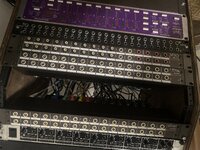
image.jpg
So from top to bottom.

M520 direct outs 1-16 normalled to Msr 16 inputs

Msr 16 tape outs 1-16 normalled to M520 tape in 1-16

Non normalled 4 track output and input (red)
(5-6 N/A) (7-8 Rca Stereo master A normalled to monitor amp inputs) (9-16 Rca 1-8 m520 program groups normalled to presonus 1-8 inputs)

(Neutrik bay) Nothing on the output 1-18 bottom input 1-8 is apogee AD8000 inputs TRS to XLR female. 9-12 output is 4 of the 8 balance amp channels from the m520. 13-16 output is headphone outputs normalled to 4 live room snake returns. 17-24 outputs are apogee AD 8000 DA outputs normalled to 13-20 m520 line inputs

(Happens with every direct out but) Say I have a Microphone on channel 4, buss assign switch 1-2 depressed for my two bus. With busses 1-2 faders up and channel 4’a faders up, monitoring busses 1-2. If I patch channel 4’s direct output to any apogee input, that is when I can hear the added distorted artifact. If I deselect the buss assign I can hear just the added distorted artifact. (Minus the regular signal because it’s not being bussed anywhere) If I disconnect this patch the artifact goes away.

Does that make sense?
 
Back
Top