Calibrated !
Well, I got some bench time last night and was able to run through the cal procedure. This post will be an outline and some general info.
the first thing to note is that my DX-4D was not really out of calibration. If this is the rule rather than the exception then your DX-2/4D should be fine as it is. (this is what I expect is true)
I used 2 pieces of test gear for this and will use them for the (future howto).
First is a multimeter that can read AC mV in the full audio range. THis is something that we all should have. By using the same meter for all calibration needs you get a consistant -10 dBv reference across all your gear.
My meter is a tek DM501 but yours could be a fluke or just about anything else so long as it reads (true) RMS AC voltages at frequences up to 20 kHz without error. (cheap meters read OK at line level 60 Hz but have significant errors above that)
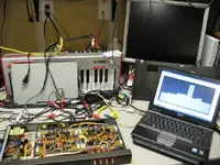
The second piece of test gear is a PC/Notebook with a sound card (don't they all now days?) running trueRTA software. TrueRTA functions as a signal generator, scope and spectrum analyser through the sound card. The 1 octave resolution version is free and will do fine for this project.
Download it here:
http://www.trueaudio.com/rta_abt1.htm
TrueRTA has the ability to measure RMS voltages but would need some calibration first... This is why I use a dedicated hardware meter.
You will also need some mini jacks (for the PC) to rca plugs. I only use one channel on the PC so as to not have to worry about the differences in sensitivity on input and level on output between the channels (left vs Right).
Here is a quick step through of the calibration procedure.
First up is the output level adjustment
1) Using trueRTA turn the signal generator on and set for 1 kHz sine wave. Adjust trueRTA's output to get 0.316 mV (-10 dBv) into your meter (you may have to adjust the volume in windows as well.) I was not able to get exactly 0.316 mV so I got it as close as my PC would allow. Remember this value. Whenever I say -10 dBv it means this value.
2) Connect the 1kHz -10 dBv signal to the DBX input 1.
3) Connect your meter to ENCODE OUT 1
4) adjust VR13 until the meter reads -10 dBv (input equals output)
Next adjust for minimum distortion
1) connect your PC line in to ENCODE OUT 1
2) Set trueRTS to spectrum analysis mode
3) you should see a large signal in the 1 kHz band and much lower signals
elsewhere (see the photo)
4) adjust VR11 to minimize all other bands except for the 1 kHz Band.
Next adjust for Symmetry
1) change the signal to 100 Hz at -10 dBv
2) set trueRTA to scope mode
3) connect PC line in to TP-1
4) adjust sensitivty until you can see a trace on the scope (it is around 5mV)
5) adjust VR12 to give the most symmetrical looking waveform.
Return to level adjustment - Distortion and symmetry adjustments change te level settings. So you have to go back and do Output Level adjustments again.
Do this for each channel and then you move on to the decode section and do the same thing. It is outlined in section 6 of the DX2/4 manual.
There are some checks you can do for Frequency response, signal to noise ratio, linearity and Release rate. I'll write about them soon and get this all on the web page.
Regards, Ethan