Tascam 388 problems Part 2

  • Thread starter Thread starter The Great Cobb
  • Start date Start date
Much better to be sorry for being thorough than SORRY

Nope. You leave the power supply installed but the box open to you can get to it. It needs to be in working order while measuring. Getting to what youu need to measure can be difficult at times.

I tend to use an alligator clip jumper wire to connect the black (negative) input wire to the chassis. This way I only have one probe to manage. Of course you need to place them where they don't short things out if they move.

Depending on the thickness of your probe tips you may be able to slide it up into the plug along the wire until it touched the metal connector inside. OR locate the trace on the PCB that comes off that pin.

In any case, the PSU needs to be powered and connected to the rest of the system except for test 3 where you remove one of the connectors on the PSU. Actually, you might want to do that first and see if it over heats.

Regards, Ethan

N.B.

PSU - Power Supply Unit
PCB - Printed Circuit Board
 
Test 3 first

"Test 3: remove PS connector P4 and see if the heatsink gets hot. P5 sends the + and - 15 volts to the system. By pulling the plug you isolate the PS from the system. If it gets hot then the problem in on the PS board. If it is cool then the problem is in the system somewhere...."


Since the P4 is what the card plugs into, and i cant plug it in without plugging them all in (P2-P6), how do i go about unplugging just that one? Do you mean to pull the entire card and power it on?

Also, when you say PS, do you mean the power supply PCB?

The reason i ask this is because the card plugs in to either all or none.

MAJOR thanks for patience...
 
Interesting, I've never seen inside on so don't know the layout. It looked from the schematic that there was a number of connectors. And I assumed that the PS PCB was mounted with standoffs and that there were 6 or so connectors that plugged into it.

I'll have to look at the exploded diagrams to get the payout of the land.

--Ethan


PS is the whole power supply which includes the series pass transistors and 3 terminal voltage regulators on the heatsink and the transformer. The PS PCB is just the board.

REgards, Ethan


"Test 3: remove PS connector P4 and see if the heatsink gets hot. P5 sends the + and - 15 volts to the system. By pulling the plug you isolate the PS from the system. If it gets hot then the problem in on the PS board. If it is cool then the problem is in the system somewhere...."


Since the P4 is what the card plugs into, and i cant plug it in without plugging them all in (P2-P6), how do i go about unplugging just that one? Do you mean to pull the entire card and power it on?

Also, when you say PS, do you mean the power supply PCB?

The reason i ask this is because the card plugs in to either all or none.

MAJOR thanks for patience...
 
Gents,

I'll be of more help when back home next week.

Ethan, the PSU PCB is of the plugin sort so the only way cobb can disconnect one connector is to jumper the connections to be left intact for the test. Cobb, I'll await Ethan's advisement but I *think* it'd be pretty quick and easy for me to make some jumper connectors so you can have the power supply card out of the unit but still connected and then be able to disconnect one or more of the connections.

Also, to assist in getting to Q1, Q2 etc., look on the back...the heatsink attaches to the chassis with just two screws. Take those out and you can tip the heatsink out and better access that tranasistors and the PCB to which they are attached. Do this with the 388 off and disconnected from the mains so you can properly position the heatsink and do whatever you have to to ensure nothing short circuits when you turn it on. I really like using that mesh rubber shelf grippy stuff you can get in rolls in the housewares section at, say, Wal Mart. Non-conductive and keeps stuff from sliding around.
 
Ah

I see it now. the PSU plugs into the motherboard.... Oh well. One could unsolder the connector on the PSU PCB but that is a bit invasive....

We will see if Cory can come up with a jumper so that the PSU board can be removed from the system and then isolate the +-15 volts to the PSU.

Regards, Ethan
 
On a much lighter 388 note, here is an album recorded using a 388. Sounds fantastic to me. Especially track 8. If you listen closely the echo and drum tone is almost exactly like the drum and echo tone on the album "King Tubby Meets Rockers Up Town" on the last 2 tracks, which is a massive compliment.

http://music.myspace.com/index.cfm?...lbums&artistid=18335382&ap=0&albumid=11700110

Hey Mr. Cobb, Can you post the link for the analog recordings in the (Post your analog recordings here) thread. We need new posters their.
 
Working on a set of extender cables for Cobbs 388 power supply. Rounded up some connectors and wiring to connect to the PSU connectors on the motherboard...now to find the ends that connect to the PSU PCB and put it all together and send it off...
 
thanks

You have no idea how much this is going to help me. THANK YOU!
 
1 down, 4 to go...

IMG_5655_1_1.JPG
 
sweetbeats

I used to think you were amazing when you were going all out to fix all your equipment... but to go all out to fix someone elses is a complete and total mindblow on a whole other level.

I appreciate it, and im going to owe you a big one. Im half tempted to snap off my Tascam M30 nameplate and send it to you so you can make your custom M-__ nameplate.
 
Don't snap anything off for me...I'm not that cool. :o

Look at it this way: the plan here is that I make these extender cables and send them to you. You use them for as long as needed. Hopefully we get your 388 going with them. Then you send them back. I may need them someday OR somebody else may stumble on this thread with a 388 PSU problem and then they PM me and I loan the cables out to them...the gift that keeps on giving.

Several folks here, particularly evm1024, have helped me out in ways that are bigger than making these cables because my problems were also complete stumpers to me, and they were big...customizing a power supply for a one-of-a-kind mixer with no schematics and then tesing out problems that arose after the power up for instance. They paid it forward so here's one way I can keep that going. I have a vested interest because the 388 is way cool and I want to see yours running and by doing this it may help other community members out in the future. Plus it propogates the kindness and help that has been extended to me, so it is the least I can do.

A couple-three more days and I should have the cables done. I'll test them with my multimeter and then I'll do a functional test on my 388. I want to make sure they aren't going to blow anything else up. :)
 
sure

Yeah i figured id send them back to you after i used them, that way they retain their usefullness.

By the way, if anyone had wondered, the name "The Great Cobb" refers to a character from the Ren and Stimpy show named "Wilbur Cobb". Hes this massive old man who's body falls apart as he speaks nonsense. He says things like "Mae West? ...Hell of a guy!" and, "SSHHHH! The walls have teeth", and basically states things that seem like utter insanity yet sometimes reek of brilliance.

My favorite line of his is "Its easy to be a genius. All you have to do is say everything stinks... that way yer never wrong."

So thats where the name comes from.
 
They work...

IMG_5885_7_1.JPG


I'll get some more detail up in the next day or two and the extender cables will be on their way to you tomorrow or Monday. ;)
 
Wow

Massive weight starting to lift off my chest, man... thank you.
 
Okay.

Here is a little tutorial on the extender cables which should be going out Monday...this is an XviD format MPEG video so you'll need an XviD codec to view. It is about 50Mb in size. This is for Cobb and anybody in the future that needs to borrow these cables. I just want people to understand the risks of using these home-grown cables, and the precautions you should take...a momentary lapse of care could do a lot of damage...I know this first-hand (from my Tascam 58), so let's be careful out there huh? I assume no liability for bad things that may result to your equipment as a result of using these cables. I sincerely hope these only bring good things, but I can't be responsible for what you do with them. Here's the vid:

https://www.torridheatstudios.com/ftp/share/movies/Tascam%20388/PSU%20PCB%20Extender%20Cable%20Primer.avi


First, let's plug in the motherboard ends of the extender cables. The motherboard ends of the extender cables connect to the motherboard in an orientation like the connectors that are on the PCB...the PCB connectors have two tabs on the bottom...the connectors I used for the motherboard end of the extender cables also have two tabs on the bottom of them. If you pay attention to how the PCB connectors are oriented when you plug the PCB into the motherboard and plug the extender cables in with the same orientation (i.e. the two tabs of each connector face the left end of the 388) you will be fine. In this picture I am holding the motherboard end of the P6 extender cable next to the P6 connector on the PCB so you can see what I'm talking about when I say "two tabs":

IMG_5880_4_1.JPG


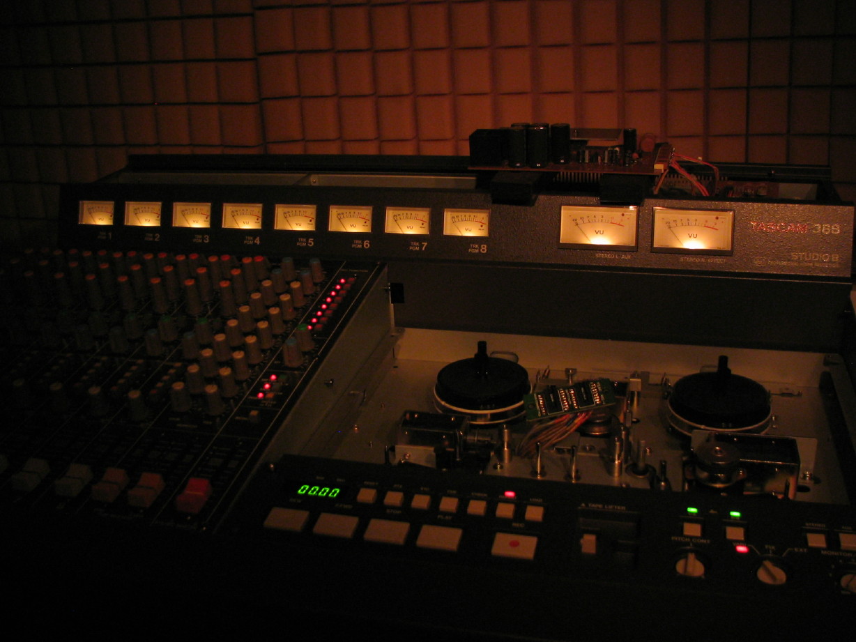
Here is a shot looking down into the cardbay at the motherboard...you can see the 5 extender cables plugged into P2 ~ P6 on the motherboard. Note that on the motherboard connectors P2 ~ P6 are labeled, but pin 1 is not identified for any of them, so just pay special attention to how the PCB plugs in and keep pin 1 of each extender cable oriented with what naturally has to be pin 1 on the motherboard since the card will only plug in one way. I'm emphasizing all this over and over because, while the card will only plug into the motherboard one way, we are removing that safety net when using the extender cables. Make sure that the motherboard end of the extender cables are not offset on the connectors on the motherboard. The labeling of the connectors on the extender cables will face the right side of the 388 (i.e. toward the power transformer), and the double tabbed side of the extender cable connectors will face the left of the 388. **Note: you will probably want to remove the Reel Servo PCB to get better access to the PSU PCB connectors of the motherboard...the Reel Servo PCB is the one just to the left of the PSU PCB. Just unplug it and slide it out like the PSU PCB and set it aside to make it easier to plug the extender cables in and see what you are doing.

IMG_5882_5_1.JPG


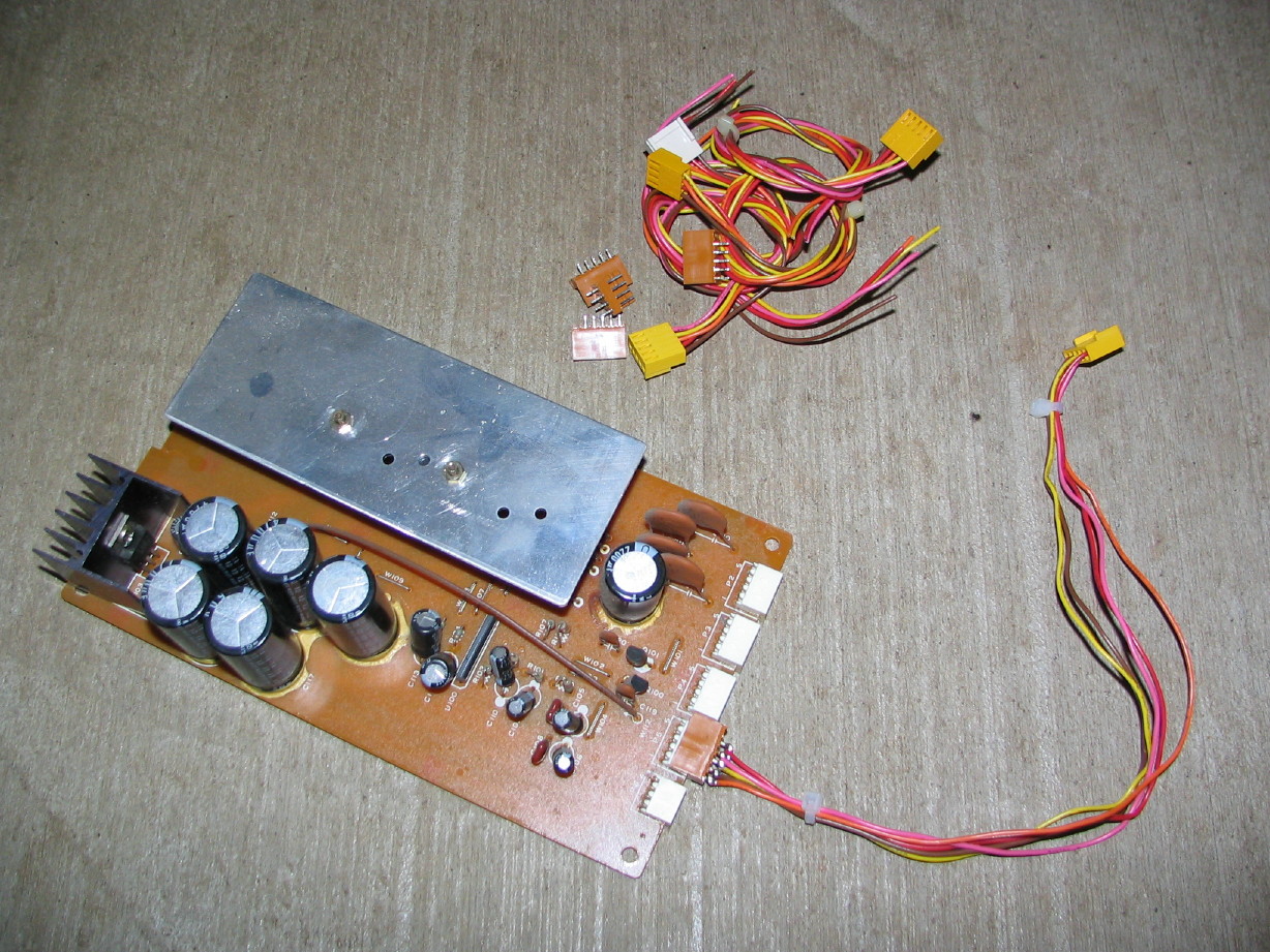
Now let's connect them up to the PSU PCB. Here's how they look when connected to the PSU PCB. Note that the "1" mark on each extender cable plug lines up with the pin 1 indicator on the PCB. Also note they are labeled P2 ~ P6 just like the PSU PCB and the motherboard. Keep P2 with P2 from motherboard to PSU PCB, P3 wih P3, etc. **Also note that the plugs for P2 ~ P5 are 5-pin connectors but I had to use 6-pin plugs.**. I had to use what I had on-hand and I didn't have any 5-pin connectors. I cut a notch out of each one to visually distinguish the unused pin location (and I also removed the pin but the risk is that you could still accidentally offset a plug so pay attention to this when connecting the cables up to the PCB!

IMG_5878_2_1.JPG


Another view:

IMG_5879_3_1.JPG


Now with everything connected up it should look like this:

IMG_5883_6_1.JPG


**NOTE: find something non-conductive to set on the top of the cardbay to make a spot for the PCB to sit...

Let me know if you have any questions.

And if I didn't mention it already, take your time, be careful, check, recheck and then check again.

BTW, since taking the pictures I have applied some RTV sealant to the terminal/solder-side of the PCB end of the extender cables.
 
Here's my little tutorial:...

Plug them in right the first time or....
PzzzzzZaaappp! Ffffffftttt!:eek:;)
 
connectors

Dont worry man, im going to read, reread, and reread as well as watch the video many times before i do anything. It seems fairly simple as long as you pay attention, but i will still be overly cautious.

Thank you.
 
Cables away!

They're on the way via Priority Mail.

We'll be watching...
 
ok

OK , I had a little time to look at the schematic. Fuse F2 and F3 protect the transformer winding for the (presumed 15) plus and minus 15 volt supply. This winding goes through those fuses and into a bridge rectifier. This provides unregulated + and - DC to the dual tracking voltage regulator chip (U100 I think) and to their series pass transistors Q1 for +15 and Q2 for -15.

I assume that you do not hear a loud hum so this tells me that the bridge is most likely not blown. If it were I would expect lots of hum....

Test 1: Measure the voltage on the collectors of Q1 and Q2 relative to ground. You should be able to see those voltages on PS connector P4 pins 2 and 5. I'm guessing that they should be around 20 volts DC or so. I'm looking for differences in the voltages, one should be + and the other - to the chassis.

That fuse F3 is blowing first may only mean that it went before F2....

Test 2: Measure the dc voltage on connector P5 pins 3 and 2 (to ground again). Should be + 15 and -15

Test 3: remove PS connector P4 and see if the heatsink gets hot. P5 sends the + and - 15 volts to the system. By pulling the plug you isolate the PS from the system. If it gets hot then the problem in on the PS board. If it is cool then the problem is in the system somewhere....

Test 4: remeasure the dc voltage on connector P5 pins 3 and 2 (to ground again). On the PS board. We are looking for a difference to the results of test 2.

Caution: be careful not to short anything :eek: (like yourself!)

Regards, Ethan


So, once i get it, and its all hooked correctly, should i power it on after unplugging P4 and see if it gets hot? The above post says "remove connector P4", but then right after he says P5 so im unsure which one im supposed to try first.

Basically my question is this, once it is connected, what should be the first test i make, and what is it im looking for?

Thanks
 
Cobb,

In "Test 3" he means to say "P4" both times. P4 feeds the +/-15V to the system and by unplugging P4 you separate the +/-15V supply from the system. Then if the heatsink still gets hot we can surmise that the issue is not in the system, but somewhere in the supply.

Do all those tests and report back. Post ANY questions you have about the tests or as questions arise while conducting the tests. Be patient and sure before proceeding on anything. I'm setting it up so I get email notices on replies to this thread so I'll be watching.
 
Back
Top