Tascam 388 buzzing through Mains and Monitor out, but not through headphones.

SwisherSweet

New member
Hi folks!

My Tascam 388 has buzzing out of the mains and monitor outs. There's no buzzing out of the headphone jacks. I tried different cables, and even outputted the monitor RCA outs to a clean mixer known to not have buzzing, and it still buzzes.

With all the faders turned down (including main stereo mix), there is no buzzing. However, as soon as I turn up the main stereo mix, there's buzzing from the mains and monitor outs in proportion to the fader being raised.

I recently had this serviced and was told that it had been recapped. Since the service, I got busy and never really used it until today, when I discovered the buzzing.

Any idea what might be causing the buzzing? I've linked a video demonstrating the problem. Behind the buzzing there appears to be a slow latching effect where the buzzing changes a bit.


Any advise / suggestions is greatly appreciated.

Thanks!
 
Hi @sweetbeats. I found a video on your YouTube channel that shows that the PCB assembly for the power supply is a pull our card:


I will pull it today or tomorrow and get some good pics of it.

Curious, are you thinking there's an issue with the power supply? If so, wouldn't that effect the headphone out too?

Appreciate your help.

- Matt
 
I did a little more testing. I ran the headphone out to a splitter cable, then into another mixer. I hear the same buzzing as I do in the main and monitor outs. So I tried the headphones again, and I if I turn the Main mix all the way up and then turn up the monitor volume, I hear the buzzing loud and clear.

I also did the same testing on another power source, an APC 1500 UPS connected to another wall. No change.

From the pics, it does look like the power supply caps were replaced, but I can't say if any other caps were also replaced.

Thank you.
 
Last edited:
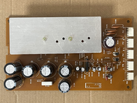
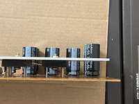
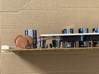
I agree, it looks like the power supply PCB assembly was recapped…I can’t verify all the caps were replaced…maybe you can. And I can’t verify the correct values were used, so you may want to double-check that against the parts list or schematic. So that’s probably what I would do first, just to verify that.

The real thing to do here is to probe the power supply outputs with an oscilloscope to look for AC components on the DC power rails. The DC power rails, and we are talking particularly about the +/-15V rails for the audio circuitry, should be clean DC and stable. When filter caps fail on a linear power supply, that can allow a large amount of AC ripple to make it through to the power supply output. And by fail I mean drift out of spec enough that the filter cap can’t keep up with the time constant of the AC wave. And this can be the case if the caps weren’t replaced with caps of the proper value too. The other thing that can happen is a bridge rectifier can go bad. But the way to know this is to scope the rails.

The reason I’m steering you to the power supply first is…that’s what you do. If you’re having trouble with a device, it’s never wrong to start by verifying the power supply is doing the correct power supply things…outputting the correct type and voltage of power, and that it is stable and clean. And in your case, because you have hum, and what sounds like 120Hz hum, across all your outputs, I’d definitely be starting at the head waters and checking out the power supply. I wasn’t daunted by the fact your headphone out was initially reported as clean. I suspected if things were setup to verify that, when cranked you’d hear the hum. And even if you didn’t that still wouldn’t dissuade me from checking the power supply. Here’s why: all the active devices in the audio path, like the opamps, are powered by the same +/-15V power rails. Active devices like opamps have the ability, to varying degrees depending on the part, to reject stuff like AC ripple or noise in the power supply. This is what the CMRR spec of a part references. But if it’s too much ripple it exceeds the part’s ability to reject the noise and it passes through the part into its output(s)…the headphone amp is made up of a pair of 386 opamps, one for each channel. These 386 parts are powered by +6V. So there is a 7806 regulator in series with the +15V power rail upstream of the 386 parts…+15V at the input, +6V at the output. Regulators like the 78xx series are designed to deal with some AC ripple at their input, and output clean DC. You’ll find it typical in a garden-variety linear power supply it goes from power transformer to rectifier, then primary filter caps and often secondary smaller filter caps, then the regulator. There is a normal amount of ripple at the output of the rectifier, and still some after the primary and secondary filters…the regulator does the rest, and then there ideally should be another small filter cap at the output of the regulator and then a small value film cap at the end of the line to shunt HF noise. And then as the power goes to each PCB assembly you often see small filter caps along with sometimes a film cap where the power comes into each PCB for more filtering. And if the design engineers got their way over the bean counters you might even see filter caps at each opamp’s or group of opamps’ power supply inputs for filtering right at each device…I suspect you have a failure of some component or components in your power supply affecting one or both audio power rails, but the headphone amp’s 7806 regulator is dealing with some of that for the headphone circuit…plus there’s a 100uF filter cap at the output of the regulator. So the noise is less. But when you crank the headphone amp you can hear hum, yes? So the ripple is bad enough even all that can’t mitigate it.

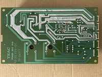
SO…check to verify the part values on the recap job are correct. Verify each electrolytic cap was replaced. It’s rare, but even new caps can be off-spec. I’ve never had this issue with the Nichicon caps I use. But it’s possible. Do you have or know anybody with an oscilloscope? You can reinstall the power supply PCB, tip the 388 on its side, remove the bottom panel and access the solder joints on the motherboard for the outputs of the +/-15V rails and scope them right there. This doesn’t give you the ability to trace upstream and find the specific fault…you’d have to have the extender board or make a set of extender cables for the power supply so you could have it connected but out of the machine to access the whole PCB assembly, but probing the outputs will give you a good start to identify if the power supply is throwing ripple. As a more coarse test, if you have a multimeter, you can set it to AC volts, put the common probe on the ground pin of the power rails’ outputs, and then check the +15V and then -15V outputs with the other probe. There should ideally be 0.00V AC at the outputs.

Hope that helps.
 
Thank you, @sweetbeats. I appreciated the detailed response. I have some basic electronic skills and I do have a Hantek 2D72. I also have the operation maintenance manual with schematics and should have the parts lists for the components used in the power supply. I'll start with verifying the caps are the correct ones, correct polarity, and then if all that checks out, scope out the +/-15V rails to see if I see any AC wobble.

Thanks again!
 
@sweetbeats I was able to measure the voltages on P5 and here's what I found:

P5-2: -15V
P5-3: +15V
P5-4: +17.8V

The first two were nearly perfect. The last one might be too high?

Also, I scoped all three and found some wobble, although I wasn't able to determine the amplitude of the signal. But there was a sign wave and I created a short video of this:


Do I need to be scoping other pins as well? I can't tell which pins go to the analog paths and should be stable.

Note, I have not verified the cap values yet. I figured I'd see if the voltages were correct and stable first.

Thanks.
 
Last edited:
By “wobble” you mean ripple, yes?

That’s not a sine wave. That looks like a triangle or sawtooth wave but it’s really hard to see it in the video. And I can’t really comment on it because I have no idea how far zoomed in you are on the VOLTS/DIV scale…the vertical scale. You need to look at what you have the scale set to, how many volts per division on the graticule, so you can estimate the peak-to-peak voltage of the waveform. It would also be helpful to do the same for the TIME/DIV scale, the horizontal scale, so we could know the frequency of the waveform. That’s the whole point…not to just arrive at the conclusion of “there’s something”, but to arrive at the conclusion of, if there IS something, it’s properties so we can form next steps. If you you are zoomed in deep on both scales you might just be looking at high frequency noise.

Is the diagnostic tool battery powered, or does it plug into the wall outlet? And I can see in the video but is there a ground clip on your probe and if so what happens to the waveform on the display if the ground clip is clipped to the 388 chassis?

We are looking for 60Hz or 120Hz waveforms, either whole or truncated.

P5-2 and P5-3 are what we are interested in…for the purposes of your current issue we don’t care about P5-4.

What happens if you measure AC volts between P5-1 & P5-2, and also P5-1 & P5-3?
 
@sweetbeats thank you. I measured the AC voltage between P5-1 (GND) and P5-2 and it was around 0.02VAC. The same was true for P5-1 (GND) and P5-3 (0.02VAC). The DC voltages were -15V and +14.94V respectively.

With respect to the scoped values, here's pin P5-3 below. The scope is set to AC coupling. The vertical scale is 20mV, so I estimate the peek to peek to be about 20mV. The horizontal scale is 10ns, from what I can tell. Honestly, I don't know how to convert this to a frequency. It seems that to complete one waveform cycle, it takes about 30ns, but I might be wrong. I figured there would be a way to measure frequency with this thing, but I am admittedly a novice at using this scope.

Hopefully this reveals some more clues.

Thanks again!

1701819643899.png
 
For all intents and purposes your audio power rails are clean…what you are seeing is likely HF environmental noise interference.
 
For all intents and purposes your audio power rails are clean…what you are seeing is likely HF environmental noise interference.
Thanks @sweetbeats. So that I'm clear, you are suggesting that the faint signal I'm picking up on the scope is HF environmental noise interference, correct?

If so, I guess that's both good news and bad news. If the power supply is not the culprit, do you have any thoughts on what else could be causing the buzzing?

Thank you for your help.
 
Well, I believe I figured it out. It doesn't appear to be caused by the 388 at all. I thought I eliminated all the variables when reproducing the problem, but I guess I forgot to disconnect a long set of XLR cables running out of my Model 16 into channel 7 and 8 of the 388. When those cables are connected to the 388 and the Model 16, even when the Model 16 is off, and channel 7 and 8 on the 388 is turned all the way down, the buzz/hum occurs. If I disconnect the cables from the 388, the buzz is gone. If I leave the cables connected to the 388 and I disconnect them from the Model 16, the buzz is gone.

So it seems that connecting the Model 16 main XLR outs to the Tascam 388 is causing the buzz.
 
The XLR inputs of the 388 are microphone level only, not line level, which is what the outputs of the Model 16 are. And depending on how chassis and signal grounding are handled between the two devices, noise and ground looping can occur…and a mic amp will amplify that unwanted signal greatly on an inappropriately connect line-level source. You could likely lift pin 1 at the Model 16 and mitigate the noise, but, again, connecting a line level source to a microphone preamplifier input is a no-no.

To your earlier post, yes I was suggesting what you saw on the scope as environment HF noise. Are you sure your horizontal scale is in nanoseconds? Your device is a 70MHz device…20ns is in the GHz range and it would be odd for a device to have a scale setting on order of 1000x more fine than the rated range of the device.
 
Back
Top