Speaker Cabinet Wiring Nightmare!!! Help!!!!!

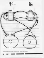
so here's a diagram i drew of how my cab is wired. each speaker is 8 ohms... the jacks are setup so that when a cable is plugged in, it breaks the connection between the right and left side of that jack (leaving the right side active and the left side dead).

obviously, the 4 ohm jack doesnt work and the 16 ohm jack only gets sound out of 1 speaker. i emailed the guy who built the cab, but he hasn't gotten back to me and i need this cabinet to be in action by wed....

can anyone make sense of what i need to do to this thing to get BOTH the 4 and 16 ohm jacks working?
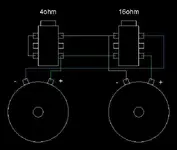
 

Attachments

  • wiring-1.jpg
    wiring-1.jpg
    57 KB · Views: 84
Why don't you just pick an impedance and wire it one way? (I tried to figure it out in my head, but I broke my brain doing that)
 
because sometimes i use a bandmaster and sometimes i use an orange. (4 ohms and 16 ohms respectively)

I don't see how you could figure it out without knowing how those jacks are internally wired. It looks like the one on the left has its tip and sleeve shorted.

You don't have both those amps plugged in at the same time, do you? ;^)
 
yeah, need to use the orange at a rehearsal on wed, and need to bring the bandmaster to buffalo to sit in with schleigho. need a grand and change for a new macbook before the GR3 takes a front seat.
 
Don't quote me on this, but remove the one wire from the 4-ohm jack to the positive lead on the speaker '+' lead as so......
If it works, thank me later. If it stays screwed up, just remember what you paid for this great advice ;). With a good DMM you should have it solved in minutes. With just a piece of paper and real brain work involved, we're all in trouble, son.
 

Attachments

  • wiring-1.jpg
    wiring-1.jpg
    56.4 KB · Views: 70
Don't quote me on this, but remove the one wire from the 4-ohm jack to the positive lead on the speaker '+' lead as so......
no, don't remove that wire -

just disconnect it

from the positive speaker lug

and connect it to the

negative lug

of that same speaker


i think that will fix it
 
Ah! I think it might work even 'better' going to the negative lug of the other speaker! But either way, he should have it solved in no time flat.
 
OK, I know this is late, but it's right. This is assuming your jacks are either actual Cliff jacks, or jacks which have an identical layout, and it is also drawn with the jacks laying with the solder terminals facing up. This puts the switch terminals on the left side.

Oh, and if you can't be bothered, just wire the whole thing for 16 ohms. You'll loose some power with your 4 ohm cabinet, but you won't hurt it.


You just had to post a switch logic question didn't you? I can't keep away from them - my mind just works that way.


Light

"Cowards can never be moral."
M.K. Gandhi
 

Attachments

  • Speaker wireing.JPG
    Speaker wireing.JPG
    15.5 KB · Views: 29
OK, I know this is late, but it's right. This is assuming your jacks are either actual Cliff jacks, or jacks which have an identical layout, and it is also drawn with the jacks laying with the solder terminals facing up. This puts the switch terminals on the left side.

What is the internal wiring on those jacks?
 
What is the internal wiring on those jacks?

When you plug them in, the one on the right gets lifted up to break the connection with the one on the left.

At least, on the two Cliff jacks I pulled out of my amp to figure this out (they are just there to fill the holes in the face plate - I've modified that amp to the point where it barely possible to see where it started, and I now only have one input jack, which is all that I need).


Light

"Cowards can never be moral."
M.K. Gandhi
 
When you plug them in, the one on the right gets lifted up to break the connection with the one on the left.

At least, on the two Cliff jacks I pulled out of my amp to figure this out (they are just there to fill the holes in the face plate - I've modified that amp to the point where it barely possible to see where it started, and I now only have one input jack, which is all that I need).

Thanks, but that wasn't what I was asking. I would like to know the signal paths between the six pins inside the "black box" of the connector. Are they TRS or just TR? Are there make/break contacts inside? Between which pins?
 
When nothing is pluggedin, they are connected straight across. (tip left to tip right, sleeve left to sleeve right) In this situation, the ring is not used. As soon as you plug something into the jack, the connection across the jack is broken.
 
Thanks, but that wasn't what I was asking. I would like to know the signal paths between the six pins inside the "black box" of the connector. Are they TRS or just TR? Are there make/break contacts inside? Between which pins?


Ah. The bottom two are a break connection for the tip, the middle two are a break connection for the ring, and the top pair are a break connection for the sleeve. In all cases, the right side connector is the one that stays live.


Light

"Cowards can never be moral."
M.K. Gandhi
 
Back
Top