MCI Head re-lap

evm1024

New member
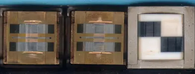
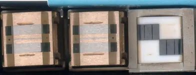
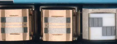
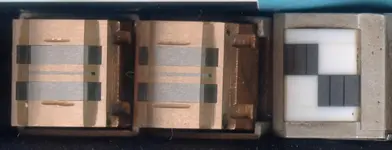
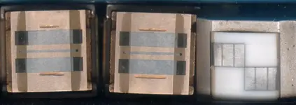
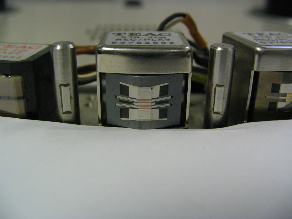
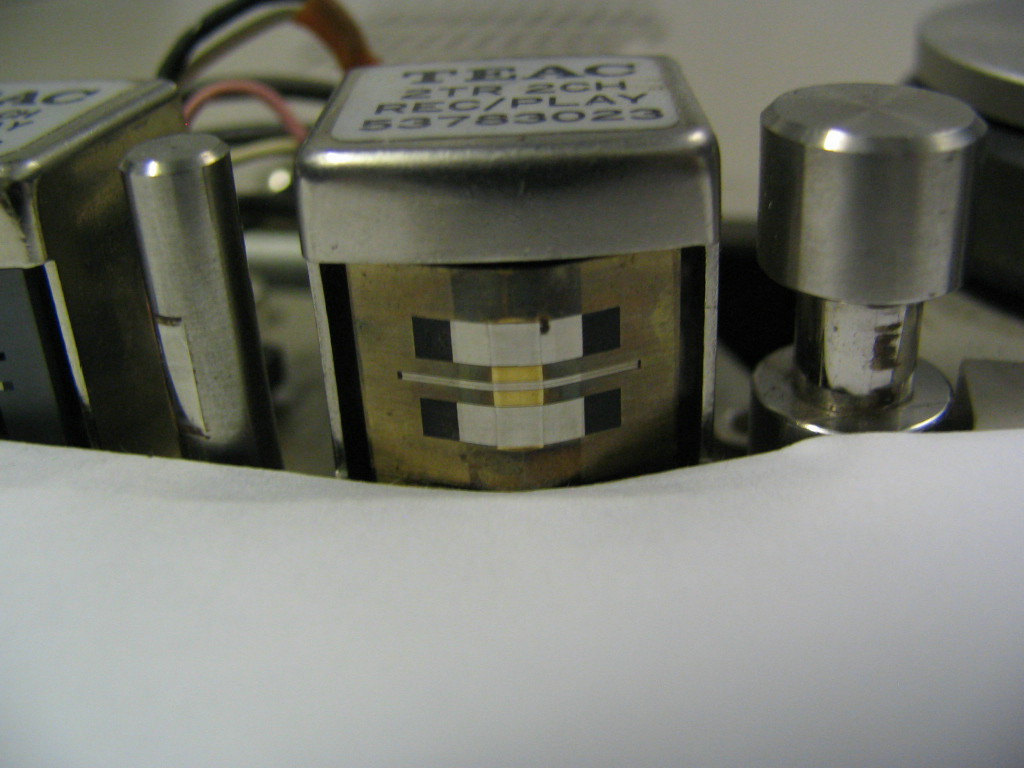
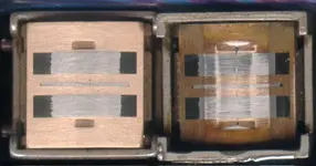
It is time to re-lap a few MCI headstacks. One is Mine and the other belongs to Jortiz. I like to get some practice in before risking an otherwise good head. I have a MCI headstack or two floating around so I have started with the most wornout one. Here is a scan of the Rec and PB heads.

The PBhead is on the right and has not been touched. As you can see the flat spot on the head goes the full width of the relief slots. It appears to be worn flat to nearly the full depth of the relief slots. And, you can see that the gap is blown out. It is so worn that the gap has started opening up. Of course it is dirty and not at all nice looking.

The left head is the Record head. It was not so worn to start with so I chose it to practice on. The gap has not started opening up yet (but given the wear on the PB head this is not too far in the future). As you can see the relief slots are about half the size the originally were. I have not started polishing this head yet. Just lapping to get rid of the flat spot and restore the original headshape. I did this by lapping the sides of the center of the head and leaving the gap area alone. As the lapping progressed the edges of the flat moved closer to the gap. I monitored the edges of the flat spot and adjusted the lapping motion to keep the flat spot edges straight, parallel to the gap and equal distances from the gap. This keeps it all centered. As the flat spot edges got closer and closer to the gap they merged at the gap and I stopped. I really do not want to take any of the gap away given the wear of this head.

I'm out of abrasives right now so this was a good time to stop. Next up in a day or 2 will be increasing fine abrasives up to 1500 grit followed by lapping film to put a nice polish on the head. I'm thinking that this will remove any remaining hint of a flat spot as well.

I'll have to cobble up an LC meter so that I can measure the inductance of the head. I do know the inductance of a new head so this might give me a hint of the remaining head life. I'm guessing that this Rec head has less than 10% (more likely < 5%) left.

In any case this is just practice with Mine and John's heads coming sometime next week or a bit later (Darn, work gets in the way). Certainly, done by the end of Feb.

regards, ethan
 

Attachments

  • MCI-heads-1.jpg
    MCI-heads-1.jpg
    61.9 KB · Views: 111
Ethan,

Thanks for posting this. It looks scary and interesting at the same time. :eek: That playback head almost looks like mine!:eek: I know it didn't have the gap though. Looking forward to more posts from this thread. Thanks again for helping out!

Best regards,

John
 
Looking forward to seeing how they come out.

I need to try and get a good shot of my heads to put them up here and get an opinion.
 
Looking forward to seeing how they come out.

I need to try and get a good shot of my heads to put them up here and get an opinion.

Steve,

To get these shots I put the heads on a flatbed scanner. It does not capture the shape of the head curve but it does get the gap well.

-Ethan
 
Ethan,

Thanks for posting this. It looks scary and interesting at the same time. :eek: That playback head almost looks like mine!:eek: I know it didn't have the gap though. Looking forward to more posts from this thread. Thanks again for helping out!

Best regards,

John

John,

Your heads are a lot better than these.... I'll post some before shots as well as progress shots.

--Ethan
 
The Re-lap is done....

I worked on these heads today. Here are some progress photos.

First up is the before photo. The heads have been removed from the head assemble and the cores removed from the outer case/shield. No wires were unsoldered and no animals were hurt. They actually do not look too bad.
 

Attachments

  • Before.jpg
    Before.jpg
    64.8 KB · Views: 84
First the hogging out

This photo shows what the heads look like after working on them with some 400 grit aluminum oxide. The goal here is to restore the original curves while removing the flat spots. This is perhaps the most time consuming part. The paper is wet and rinsed frequently and the heads are looked at often (every 4 to 6 stokes) to see that the curve is good and judge progress. You need to take off metal in a uniform way.

The flatbed scanner does not show contrast very well....
 

Attachments

  • 400.jpg
    400.jpg
    65.5 KB · Views: 84
Moving on to 600

With he flat spots removed and the curve where we want it to be we start taking out the groves that the 400 left behind. 600 grit takes the head from a clean but dull finish to a more lusterous one. It only taked 10 minutes per hed or so to shine them up.
 

Attachments

  • 600.jpg
    600.jpg
    65.8 KB · Views: 83
After 600 we move to 1500.

1500 grit starts to bring out the shine. Slow, gentle strokes with lots of rinses are the rule. A single grain of 400 can set you back to do it again. As you can see the heads are starting looking very nice.
 

Attachments

  • 1500.jpg
    1500.jpg
    63.9 KB · Views: 84
On to lapping film

With the 1500 grit behind us and the heads shining we might be tempted to stop. However we still have some 12 and 9 um lapping film to bring out a mirror like finish. THis is one of the fun parts as that the heads start to look almost new. Close inspection with a jewelers loop shows the gap. It does not show up on these scans. You do need to angle the head against the light to make the gap visible. The edges of the head paralled to the gap are cut back so thet the center portion of the head is the only part that contacts tape. Interesting way to do it. It works.
 

Attachments

  • lapped.jpg
    lapped.jpg
    64.9 KB · Views: 83
Re-assembled and partally aligned

Here the heads have been put back on the head block. The guides have been rotated and some basic adjustments done. I placed some leader tape across the guides and heads to adjust the height of each head. Once the height was set I adjusted the zenith. And lastly the wrap (Which would be tangent).

I put the headblock in my MCI and ran some tape across it a few passes (after a good demag). This added a little extra polish to the heads which showed that the wrap was off. The tape was not hitting the head centered on the gap. A little turn and things lined up nicely.

At this point I marked the head with a felt pen across the gap. Then ran some tape across it again to verify the alignment. Looking good.

The meters are bouncing with a strong signal. I did not turn on he mixer to monitor what was coming off of tape yet....
 

Attachments

  • headstack.jpg
    headstack.jpg
    66.2 KB · Views: 75
Whats next?

Good question. I've got 3 or 4 days of overload to do at work.(site visit)

It may be a few days to get back to these. Next is to run a MRL over the heads and align azimuth. Then it might be nice to do some frequency checks. And record some tones. Lastly pack it up and sent it off to jortiz.

You might have it by next Saturday. Sooner if I get time.

--Ethan

PS I'll send along some lifter sleeves as well.
 
Ethan,

The heads look great! :D:D:eek:You did a fantastic job by just looking at the pictures. Looks like they polished up really well and there wasn't anything really bad with them. I can't wait to try them out. :D:D Thanks for checking all the settings, and all the adjustments also. I really appreciate that. Nice work Ethan!!!

Best regards,

John
 
Ethan...this is just impressive and encouraging.

Everything with an analog deck comes down to the heads. An analog machine is (relatively speaking) worthless without good/functional heads and so for those of us that want our decks to go and go and go for years to come (and can't afford the luxery of having John French do our heads), it is extremely valuable to have somebody like yourself demonstrate that it really can be done to a very good result...When I read the Nortronics guide I think "man...it seems...*simple*", but there is so much taboo about touching the heads that it seems like insanity to start rubbing them on a piece of sandpaper. I realize it takes care and skill and the right setup and environment to do this...there is a right way and many wrong ways to approach it, but what you are doing is showing us that this can indeed be done at home with readily available materials, and for those of us that are bravely nuts enough to give it a shot this is encouraging. Still working on the nuts part here, though it sure would be nice to have a go at the heads on my BR-20T...I recall you invited me up for a rainy Saturday and we never got around to it...maybe not enough rain? No...we had plenty. I know...there were 200 other things to do...*sigh* :o

BR-20T%20Sync%20Head.JPG


BR-20T%20Repro%20Head.JPG
 
Sunny now

Beats, come on up. We'll have them done (or done in) in no time.

John's heads are in the mail. We will see how they work in his machine soon. They looked good in mine.

--Ethan

PS I need to measure the diameter of the lifters on my BR-20. Then if I have sleeve material we can cut some of those too.
 
How firm a fit are those sleeves? The lifter assembly need to come out to put them on? Clearance issues when retracted? I guess that's part of measuring...

Did you have a chance to do any performance measurements on John's block?
 
No Measurments

No time to do anything except to align az and run through the MRL tones and print a few test tones.

THe heads appear to playback all tones on my NAB MRL +-3 dB upto 20 kHz. Printing tones worked as well +-3 dB. The electronics are set up for my Saki heads. THis might introduce some spectrial differences.

John will let us know.

--Ethan

THe sleeves are about 10 thou in wall thickness. Lots of room there. I've been using surgical stainless steel tubes.
 
Ethan,

Thanks so much for the work on the heads! I appreciate it very much. I'll let you know when I get them and run it through my machine. Thanks for the sleeves too. Can't wait to try them out.:D

Best regards,

John
 
No way I'm doing that....:eek:

I gotta draw the line somewhere. I'll just save my pennies and send them to JRF.... Or buy new ones from Teac.
 
Back
Top