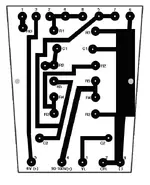
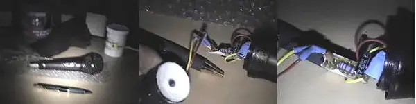
Made a mic

  • Thread starter Thread starter rory
  • Start date Start date
mshilarious said:
OK, tonight's test of the fully assembled mic:

Sensitivity is about -3dB less than the Apex 220, which would make the mic about -45dB/Pa :confused: Last night's ghetto mic was 3dB more, and I used the same capsule, just with different resistor values. I need to assemble a mic with the original resistor values and compare, because I thought the gain in capsule voltage would more than offset the signal loss to the smaller resistors :confused:

Anyway, here's a frequency response graph vs. the Apex 220. So it seems my mic is a little brighter.

I'm working on audio samples of the mic vs. the Apex and a Shure KSM141. Stay tuned!


That seems really cool.
What's the cost estimate per mic?
 
Sloan said:
That seems really cool.
What's the cost estimate per mic?

About $7 in parts, plus a clip if you don't have one (pencil condenser size).
 
I just Finnished makeing My Second Mic today but this Time I did a few Things differently....

This time I made a Small Circuit Board to Hold the Caps and resistors and I also added a Small .0001 PF Mica Cap after the 10UF Cap so to try to reduce distortion at high Frequencies...

I also put in a Small On/Off Switch to turn off the Mic and I used a Better quality XLR Connector than the One that came with the Cheapo $3 Mic i use as a Body.....

I have It powered useing 3 x 1.5v Watch batteries which last quite a Long time and I get 10 watch Batteries for $1....

This Time I mounted the element in a Bed of Silicone to make it less sensitive to Vibrations and handling Noise and it Should make the mic a Bit more Directional as the sound comeing from the Sides and Bottom is Muffled by the Silicone......

I haven"t had a Chance to use it more than checking to see if it works which it does and it seems to have a better sound than the First mic i made as the element I am useing is a Better quality one (Panasonic WM-61B) and it is Ballanced which is cool.....

My Next project I was thinking of makeing a Mic Pre-Amp as I found some Schemetics for one and it doesn"t seem that difficult nor expensive and I have a Printed Circuit board Kit arround that i can use to make the PCB....

Here are some Pics of my Latest Mic:


Cheers
Here are some Pics:
 

Attachments

  • Mike-02.webp
    Mike-02.webp
    17.5 KB · Views: 224
Minion said:
I also added a Small .0001 PF Mica Cap after the 10UF Cap so to try to reduce distortion at high Frequencies...

I assume you mean .0001uF, which is 100pF. That's too small. It will only pass very high frequencies (something like 1mHz) and thus have no effect on audio. You want to use something in the .01uF - .1uF range.

This Time I mounted the element in a Bed of Silicone to make it less sensitive to Vibrations and handling Noise and it Should make the mic a Bit more Directional as the sound comeing from the Sides and Bottom is Muffled by the Silicone......

Very good about the vibration. However that is not the way omni capsules work re: directionality. To get a directional pattern, a capsule has to let sound strike the back of the capsule to cancel out sound hitting the front. Since the Panasonic capsule isn't designed that way, it's gonna be omni pretty much no matter how it's mounted.

If you want a cardioid mic, Panasonic makes cardioid capsules.
 
I actually Have No idea about the Mica Caps as I do not understand the Codes that are written on them, the Box stated that the Cap I used was .001pF (2E102K was the Code).....

These are the Values on the box of caps in "pf" ,
0.001 ,0.0022 ,0.0033, 0.0047 ,0.0068 ,0.01 ,0.022 ,0.047, 0.068 , 0.1,0.22,0.33 ,0.47, 0.68 ,1.0 ,2.2....

Which of these should I use?? (how many pf in a uf??)

I really wish I understood electronix and am really trying to learn but everything i read on it Just Goes over my head... :confused:

Also the Ouput Impedance on my Mic is 2.2kohm ,How would I go about lowering it without negitively affecting performance??

Thanx a Lot....Cheers
 
Minion said:
I actually Have No idea about the Mica Caps as I do not understand the Codes that are written on them, the Box stated that the Cap I used was .001pF (2E102K was the Code).....

These are the Values on the box of caps in "pf" ,
0.001 ,0.0022 ,0.0033, 0.0047 ,0.0068 ,0.01 ,0.022 ,0.047, 0.068 , 0.1,0.22,0.33 ,0.47, 0.68 ,1.0 ,2.2....

Which of these should I use?? (how many pf in a uf??)

Those values are all in uF. There are 1,000,000 pF in 1 uF. 102K means 10 followed by 2 zeros, in pF, which is 1000pF or .001uF. The K is a tolerance rating, that is not important here, 2E is a temperature rating which is also not important.

You should use the largest one you can fit, .47uF might be a good choice.

Also the Ouput Impedance on my Mic is 2.2kohm ,How would I go about lowering it without negitively affecting performance??

Thanx a Lot....Cheers

You would have to add a buffer stage using transistors.
 
What program

mshilarious said:
OK, tonight's test of the fully assembled mic:

Sensitivity is about -3dB less than the Apex 220, which would make the mic about -45dB/Pa :confused: Last night's ghetto mic was 3dB more, and I used the same capsule, just with different resistor values. I need to assemble a mic with the original resistor values and compare, because I thought the gain in capsule voltage would more than offset the signal loss to the smaller resistors :confused:

Anyway, here's a frequency response graph vs. the Apex 220. So it seems my mic is a little brighter.

I'm working on audio samples of the mic vs. the Apex and a Shure KSM141. Stay tuned!

What program was used for the Graph....???? :confused:
 
SuperGeek said:
What program was used for the Graph....???? :confused:

That's from Wavelab.

One thing to keep in mind is that is not a response graph, strictly speaking, because I don't have perfectly flat monitors nor an anechoic chamber. That's why I show the comparison to a reference measurement mic, which is more or less flat. If you take the difference between the two, that gives you an idea of my mic's response.

Sorry I haven't gotten audio samples up. The mic capsule seemed to have crapped out on me; I had to replace it, and I built another one with the higher resistor values. Today I will compare & record something with the two :)
 
Just a bump to let you know I haven't abandoned this! I've been playing with the design a little more, I think I have a final design I will try out tomorrow. Also, in light of the mic's high output impedance, I ran a series of tests with my variable impedance pre from a very low 150 ohms up to 3K ohms. Essentially, I found that the mic loses a few dB, but is still OK down to about 1k ohms (-3dB). Below that, volume drops pretty drastically, down -9dB at 600 ohms and -16dB at 150 ohms.

The loss in bass response was not that dramatic, only seen below 40Hz, rolling off at about 6dB/octave, steeper at lower input impedances. Harmonic distortion at different preamp input impedances and different frequencies (40, 1K, 15K) was either similar to or superior to the Apex 220, and not notably different from low to high input impedances.

This is all fairly encouraging; if your preamp is 1.5K or higher, these will work just fine.

I know, I know--audio samples! I beg your patience as I attempt one further design improvement :o
 
Hi, I was wondering if you could help me out with something?

I have Made a few Mics Now useing different elements and Different Cap Values and Now I want to try makeing one that has 2 or more Different types of elements in it to see how that would sound...

So what I was wondering is How would i wire them up??

Would I need to use seperate caps ,resistors and Power supply for each element and wire the outputs of each to the same XLR Output or could I simply wire all of the positive leads from the Elements together and wire the Negitive leads together and then Run that through the Caps and resistors and out to the XLR and use a Stronger power supply?? Or would I have to Double or Tripple the Cap Values depending on if I were useing 2 or 3 elements ??

Any help On this would be great...

ThanX a Lot!!

PS: Post some Pics and audio samples when you get yours completed...
 
Minion said:
Would I need to use seperate caps ,resistors and Power supply for each element and wire the outputs of each to the same XLR Output or could I simply wire all of the positive leads from the Elements together and wire the Negitive leads together and then Run that through the Caps and resistors and out to the XLR and use a Stronger power supply??

You can use the same power supply, but each capsule should connect to the power supply with its own resistor(s). The power supply only needs one cap. You can connect the negative leads to ground, but the positive leads should connect together across resistors.

This diagram might be helpful:

http://www.linkwitzlab.com/images/graphics/microph2.gif

Except that is for a stereo mic. For a dual capsule mono mic, omit both R2s and connect the R1s together to the input of the preamp.
 
That helps a Lot ,I will give it a try and see how it works out...

ThanX
 
OK, here it is, finally the audio sample! Sorry I had to go on vacation :o

Dirty Blues Pickin'

This was recorded with 2 of my mics in baffled omni stereo (Jecklin disc), about 12" away from the 12th fret and soundboard, with the baffle around the 17th fret. Preamp was an ART Digital MPA. Sorry about the sloppy performance, I don't practice so much anymore as I spend all my time playing with mics :o But hey, that was all first take, which is a near record for me :o

After some more testing with the Apex 220 and Shure KSM141, I can safely say this is a better mic than the Apex. It's quieter, clearer, and a bit more sensitive. How much of that is Panasonic's improved capsule vs. my capacitors, I don't know. On the other hand, this mic won't knock my KSM141 off the stand (which is more detailed, fuller, and more musical), but for $7 in parts, it can't be beat :)

Here is the final schemo, with a few revised values. I also flipped pins 2 and 3, which makes no difference in sound, but makes it a little easier to assemble. The mic seems to be happy with input impedances over 1.3K, and doesn't really suffer until below 1K.
 
Wow!! Thats a pretty Nice Sound.....The circuit seems quite a Bit more Complex than the One I use... I wonder if there is any differance in sound between the Circuit that you use and the One I use??

I have been getting Fairly good results also with my Mics...The one Little Problem I am haveing is that it seems that these Mics have a Fairly low SPL as I can overload them pretty easilly Like when trying to Mic a Guitar cab...

So Far the Best results I have had was useing a 1Uf Mica cap after the 10Uf Electro Cap with a version of the Tape-Op circuit....I have been useing this Mic for Micing the Bass drum on my drum Kit in Combination with a Dynamic Mic and It sounds Great, It is the Best Bass drum sound I have gotten so far and it doesn"t Overload on the Bass drum.....I"m thinking of maybe trying one on the Bottom of my Snare Drum to see if I can get a better Snare sound...
They also seem to work Quite well for micing Cymbals.....

I am about to order the Parts to make myself a 4 Channel Mic Pre-amp that has Phantom power for Electret Condencers(Only about 4.5v) and will Probably eventually make a Proper 48V Phantom power supply that I can use with this Mic Pre so I can use it with real condensers....

The Schematic I have seems quite simple and the Parts only Cost about $20 per Channel ......

Cheers
 
Minion said:
Wow!! Thats a pretty Nice Sound.....The circuit seems quite a Bit more Complex than the One I use... I wonder if there is any differance in sound between the Circuit that you use and the One I use??

Sure there are differences, but they are mostly related to my use of phantom power. The major difference is the capsule itself, I would suspect.

I am about to order the Parts to make myself a 4 Channel Mic Pre-amp that has Phantom power for Electret Condencers(Only about 4.5v) and will Probably eventually make a Proper 48V Phantom power supply that I can use with this Mic Pre so I can use it with real condensers....

Since the preamp probably supplies the opamps with 12 or 15V, I can't see why it would be difficult to tap the main power rail for phantom power. Many electret condensers will happy with 12V.

Slightly more sophisticated but still cheap and easy would be to create a separate phantom rail using a voltage doubler or tripler arrangement. That way you wouldn't need a special transformer and you could still get a full 48V:

http://hyperphysics.phy-astr.gsu.edu/hbase/electronic/voldoub.html#c2
 
Thanx for the Link....In theory makeing a Voltage doubler or Tripler Looks fairly easy (useing a step-up Transformer??) accept that I wouldn"t know How to integrate it into the Current Circuit schematic I am useing and I wouldn"t know what values of Caps,Diodes ect to use....

Maybe it would be easier if I made the Voltage Doubler seperate from the Pre-Amp PCB"s and Just wire the power to the XLR Inputs and add a switch to turn it on and Off for each Channel?? But I think most of this will be Quite a Bit over my head as I can Follow a Schematic but I don"t understand the Theories that are Involved as I am very New to Electronics but verry interested in it....

The Pre-Amp I am building runs off of a 9V Battery but I was wondering if instead of useing a 9v Battery could I just use a 9v Power adapter so I can Just plug it into the wall??


ThanX a Lot....
 
Minion said:
Maybe it would be easier if I made the Voltage Doubler seperate from the Pre-Amp PCB"s and Just wire the power to the XLR Inputs and add a switch to turn it on and Off for each Channel??

Yes, that would be straightforward. If there are not already DC blocking caps in front of the pre, you would need to add those too.

But I think most of this will be Quite a Bit over my head as I can Follow a Schematic but I don"t understand the Theories that are Involved as I am very New to Electronics but verry interested in it....

Keep learning stuff, a year ago I wouldn't have been able to manage that type of mod myself.

The Pre-Amp I am building runs off of a 9V Battery but I was wondering if instead of useing a 9v Battery could I just use a 9v Power adapter so I can Just plug it into the wall??

Yes, as long as the adaptor provided enough current--which should be a piece of cake if the pre was designed for a battery.

However 9V is really low for a mic pre power supply. That is barely adequate for a -10dBV level, and inadequate for +4dBu level gear. If you stick with the batteries, use two 9V to get a +-9V supply, or better yet, build a proper +-15V supply.

With the amount of work and expense that goes into 4 channels of mic pre, skimping on the power supply is a false economy.
 
Hi, The Op-Amps used in the project i am doing can run from 2.7v to 24v so It has quite a wide power range (LM6134 Quad Low Power 10 MHz Rail-to-Rail I/O Operational Amplifier) and in it"s specs it says that it can produce 100db of Gain at 5v ,I don"t Know if i get more gain with higher voltages but I"ll have to check into that....

This is the Project i am doing:

http://orca.st.usm.edu/~jmneal/preamp1.htm

It seems easy enough for me to do, I think the hardest part will me etching my own PCB as I have never done it before, but I have a Kit with instructions so I should be able to figure it out and the whole Project only has about 50 parts per channel...The only thing I don"t get about the Pre-amp in this project is it doesn"t have a Gain Knob ,It just has a switch that goes from Off to Low Gain and to High Gain, and a LED that lights up when the signal Clips...
I"m thinking maybe I can wire up a Pot instead of just haveing just the 2 gain settings or maybe wire up 2 Pots one for Low gain and one for high gain....

It is a really simple Project and if I happen to make it through this one without to many problems maybe I"ll try makeing a Green Pre as I have allready been in contact with the person who makes the PCB"s and the Person who sells the Parts kits....


Cheers
 
Minion said:
It is a really simple Project and if I happen to make it through this one without to many problems maybe I"ll try makeing a Green Pre as I have allready been in contact with the person who makes the PCB"s and the Person who sells the Parts kits....

I think you'd be better off with the Green pre, since it has more serious features than the pre you linked (a real gain control, phantom power, and balanced inputs). Also there is an entire bulletin board practically dedicated to building the Green, so there's lots of help available.

As far as gain, that is theoretically determined by the resistor values used around the opamp, it's great to say a given opamp can do 100dB, but that's only true to the extent that the voltage supply can support the gain. If the power supply is inadequate, the opamp will clip. Higher voltage=more headroom.

The pre you linked uses a 9V supply, which is gonna limit the pre to the levels I mentioned before.

The bias arrangement confuses me. The left part of the schematic puts a regulated voltage across the mic leads (maybe for a capsule like the Panasonics that need a few volts?), which is then blocked by C9. Then it adds bias back via R7 & R8. This doesn't look like a general purpose mic preamp.

The gain switch is kinda silly, just leave it out (along with R11 and C5) and replace R10 with a 100K pot, and then change R9 to 4.7K. There's a gain control.

If you want something simpler than a Green pre, try frederic's mic pre here:

http://www.homerecording.com/bbs/showpost.php?p=1788168&postcount=12

The power supply for the Green pre will work fine for frederic's pre too. I don't think he's posted the output stage yet though.
 
Minion said:
It seems easy enough for me to do, I think the hardest part will me etching my own PCB as I have never done it before, but I have a Kit with instructions so I should be able to figure it out and the whole Project only has about 50 parts per channel...
Cheers

It's really not that bad. The weather MUST be warm to do a good job and you have to be careful with the materials. A. They taste like crap if you get the chems in your mouth. B. You have to dispose of the etching solution resposibly C. they layout has to be solid on the board. I do mine in photoshop.

I use glossy photo inkjet paper but print the circuit backwards on a laser printer. Then I tape it to the copper board and use a really hot iron and alot of pressure. The laser toner bonds to the copper. Afterwards, soak the board until the paper disolves and you have a perfectly masked board.

Here's my PCB layout for the Royer circuit.
 

Attachments

  • tube mic - flipped.webp
    tube mic - flipped.webp
    15.9 KB · Views: 200
Back
Top