*sigh*
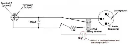
Yes, that works for the tape op mic. I am talking about a mod to use phantom power. Then the caps (plural, there must be at least two of them, if you don't use power supply filter caps) have to fit in the mic housing. Ain't much room inside an XLR connector, about 15mm L x 12mm D, and that would include the necessary resistors.
While it's true polys are superior, the reality of using a mic that is made from $10 in parts is that it's probably going into a preamp that has electros and plenty of 'em, and they probably aren't bypassed with small polys, etc.
I've got my schemo and parts list ready for the phantom version, I'll report back when I'm done. By necessity, I will have to use axial electros, and I don't have room for poly bypass caps.
I'll see what I get.
 ), if you want 3V, change the zener to 4.3V.
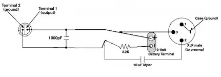

")

")