I killed my 388!

  • Thread starter Thread starter Gavin137
  • Start date Start date
G

Gavin137

New member
Maybe - I sure hope not. I recently decided to try to install led lights in the vu meters of my 388 as all the light burned out a long time ago. This 388 has been sitting for a few years, but I fired it up a few days ago to put some old tracks I had into Pro Tools. So it was working fine before I decided to open it up.

After getting the vu meters out, but leaving them still wired up I powered up the machine, thinking to measure the voltage of the lights so I could figure out what resistors I would need for the leds. As soon as I powered it up there was a buzzing sound from the area of the reel motors, the vu meters all pegged, and I later noticed that the first fuse in the fuse pcb had blown. I replaced the fuse and turned it on again, but the fuse blow almost immediately. I think I might have inadvertently shorted something out by having the meter circuit boards touch something they shouldn't have. What can I say - I'm an idiot!

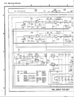
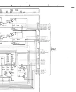
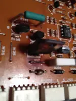
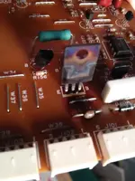
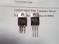
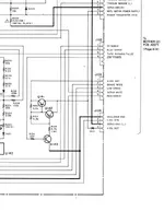
Following the wire from the fuse led me to the reel servo pcb, where I discovered a component (Q141, transistor?) that looked burned, as well as a resistor very near it. With very limited experience fixing this kind of thing, I'm wondering if I should try to replace those burned components and see if that fixes it, or if it is likely that there is another root cause why those parts burned.

I'm totally bummed that I have screwed up my perfectly good 388, and I would really appreciate any help I can get here to fix it.
 
I guess it couldn't hurt to replace the damaged components fo you can find them.And if you're confident with a soldering iron.
I'd give it a go.
 
I'm not that confident, just don't know what else to do. Right now I'm actively searching for the whole reel servo board. If anyone here has one . . .
 
OK, well since I'm not finding the whole board, I'm going to try to replace the fried components and see if that works. So, a couple of resistors that shouldn't be a problem, and a transistor 2S507B found online. I still have no idea if the fuse keeps blowing because of the transistor, or whether the fuse and transistor went because of some other problem. Guess I'll find out soon enough.

I haven't tried to solder directly on a circuit board since high school, when I built a kit radio that would only pick up the station from Tijuana, so skills could be lacking. Maybe I'll practice on an old junk board.
 
Do you have a schematic and service manual for the 388. If not, before proceeding, get one. TEAC parts in Montebello, should have, it will cost but it is critical you have this.

I don't know a lot about how these are setup. If you can disconnect the power supply altogether or at least from the board with the fried parts do that, then test the power supply by itself. Often times you get cascading faults, a failed part causes a short here, burns out a part there. It is possible that transistor failed, but you also don't want to replace it without knowing why that fuse is blowing, or if something else (e.g. a capacitor somewhere else) failed causing a short somewhere. Again, I'm not familiar with the internals of the 388. I'd start at the power supply verify approximately proper voltages and work my way toward the fried parts board.
 
Thanks for the advice. I do have a schematics for all the boards in this unit, and fortunately they pull out very easily, so it would be no problem to test the output of the power supply without the reel servo pcb connected. I'll do that this evening, and I can do plenty of other testing while I'm waiting for parts to arrive.
 
looking at the schematics I can see that the circuit with the blown transistor lies in between the power supply to the reel motors. And not too surprising since the motors did some really jerky back-and-forth movements right before the fuse blew. This circuit is also connected to the transport controls, so it must allow power from the power supply to the motors. The portion of the circuit on the pcb consists of three transistors, three resistors and a diode. Tracing back through the power supply it runs back to the fuse that blew, so I'm pretty sure I'm on the right track, although I still don't know what caused the problem in the first place. Tomorrow I'm going to test the power supply and make sure it's putting out the 35 volts it's supposed to at that connector.
 
Being pretty inexperienced at this kind of thing I'm not sure how to go about testing the power supply. Obviously it has to be in the machine to get power to it, and then it's going to be connected to everything except the reel servo pcb which is pulled out at the moment. I did power up the machine with the fuse replaced and the reel servo pcb out: no blown fuses, no lights or indicators of power at all. Then I soldered in a new transistor to replace the one that was bad, and when I powered it on 2 fuses blew right away, and a puff of smoke from the area of the transistor I just replaced.

So obviously there is more wrong than just the one transistor, but I have no idea how to track it down.
 
Did you test the PSU unconnected to see if it more or less is working properly? If it's modular, disconnect the power supply altogether from the back plane, cable or however. Then turn on and see if the fuses blow. Is the section with the blown transistor also modular (can you remove the board it's connected to) and see if the fuses blow.

Forgive the obvious question, but are you sure you soldered in the transistor in the correct orientation (base,emitter,collector) there may be different pinouts depending on whether you got an equiv part or an exact manufacturer match.


Also, could you scan the section of schematic and post here?
 
I did power up the unit with the reel servo pcb pulled out, and no fuses blew. As soon as I replaced that pcb the fuses blew.

I thought I was installing the transistor correctly, as I took a picture of the blown one to make sure I put it in right, but It had not occurred to me that the pins on the replacement might be different from the original. Is there a method for testing transistors to see which pin is which?

I'm not sure if I have a high enough post count to post pictures yet, but I'm going to give it a shot.

BTW, I really appreciate your taking the time to help me with this.
 

Attachments

  • Part 1.webp
    Part 1.webp
    38.2 KB · Views: 123
  • Part 2.webp
    Part 2.webp
    33.3 KB · Views: 121
This is a schematic from a scanned manual I found online. I'm going to see if I can get a clearer scan from my paper manual if I can find it. The blown transistor is Q141, located on the lower right of the larger schematic.
 
here is the board in question.
 

Attachments

  • board1.webp
    board1.webp
    29 KB · Views: 73
  • board2.webp
    board2.webp
    29.6 KB · Views: 79
What part did you get to replace Q141?

The stock part is a 2sb507 pnp power transistor with 1b, 2c, 3e pinout reading left to right when looking at the face of the transistor. If you got something with a different pinout then, yeah, at the least it won't work and at worst it'll take other parts down with it.

I made some extender cables for the PSU in the 388 but loaned them out and never got them back. It allowed you to truly isolate the psu from the rest of the system for testing which you can't do with it plugged into the motherboard. The cables allowed the psu card to receive its inputs but left outputs disconnected.
 
Sweetbeats, I followed your 388 story with great interest, so thanks for your help here; greatly appreciated!

Here are the transistors, original on the left, replacement on the right. I ordered 3 of them in case something went wrong. Ordered from FPIE Electronics.

Great idea to build an extender cable to get the PSU isolated. I'm not sure how to test otherwise, except as I mentioned, when I powered it up without the problem board installed no fuses blew. Visually I can't see anything wrong, except some diodes that look like they might have gotten hot at some point.
 

Attachments

  • transistor.webp
    transistor.webp
    28.4 KB · Views: 75
Here is a clearer scan of that part of the schematic. I'm wondering if maybe I should replace that whole circuit, including Q141-143, R153-156, and D141. I have not been able to find a match for that diode, and I can't really read the numbers on the part itself because it is somewhat blackened. I tested it in the circuit, and it passed current one direction and not in the other, so I thought it was probably ok.
 

Attachments

  • circuit1.webp
    circuit1.webp
    29.4 KB · Views: 73
Answer these questions:

1. With the reel servo card out is the capstan spinning up okay? Is it steady and is the pitch control working okay?
2. Just to confirm, its F1 that blows when you put the reel servo card in?

So, okay...

I don't know why I didn't see it before...D141 looks like its full of pus and needs to be lanced. Replace it. Q141 and D141 sit on the +35V unregulated rail so when the event occured there was healthy juice there. Also, look at the wire link W17...that sucker was on its way to being a fuse link, man. See how the board got hot around it? Check the solder joints on the link. You may need to do some repairs there if the lands are damaged, like shave back the coating to healthy trace material, tin it and bend the leads of the new part over so you can solder to healthy traces.

Aside from the above, if it were me I'd be replacing everything in that loop on the servo board simply because I don't have the right gear and knowledge to test Q142 and Q143 out to make sure they are still healthy, and because something went sideways on a +35V rail and heated stuff up pretty good, and because we're dealing with 25 year old components that have been exposed to stress I'd make sure Q141, Q142 and Q143 are new parts as well as D141, and R153, R154, R155 and R156. And check out W17 like I said...and any other wire links that are associated with that circuit. My copies of the pcb layouts are pretty ugly so I can't tell for sure but maybe W35 is part of that section?

Make SURE you triple-check the pinouts for the transistors you buy against the schematic and the actual board...it would suck to put the new part in with the wrong orientation even though the package of the part matches the little picture on the board. Don't trust in that. get the datasheets for the parts you get and understand what pin does what on the new part and compare to what trace does what on the board and then match them up. Also make sure you get the right resistor for R155...needs to be flameproof 1W.
 
Without the reel servo board in place absolutely nothing happens when I power it up - no capstan motion, no lights, no blown fuses. The first fuse to blow was F1, but the next time (after I replaced Q141) both F1 and F2 blew.

My plan is to replace everything in that part of the circuit. D141 has an identification number of 1R5DZ61, which not yielded much info as far as what to replace it with. I'm pretty sure I will have to re-tin some of the traces as you say, because of the heat damage.

Other than that, once I rebuild that circuit I still don't know that it wasn't something farther down the line that caused the problem, such as a short in the motors or associated wiring.

BTW, I have a paper manual in good shape if anyone needs good scans of any of the pages.
 
I'm not positive but I think the capstan should spin up even with the reel servo pcb pulled.

My advice at this point is to build some extender cables to isolate the psu and test it, not just for proper voltage but test for AC on the DC rails.
 
Correction: I had the PSU installed wrong! So, with PSU installed correctly and the servo board out of the unit when power up not only does the capstan spin, but the machine went into play mode, with the pinch roller snapping into place very briefly before F1 blew again.

I have located another servo board, so if I could run down what this problem is I think I could get this thing up and running again. Per sweetbeats' suggestion I think I will build the extender cables so I can isolate and test the PSU.
 
Yeah, I really think that would be wise. Post here if/when you need advice on the extender cables or if you need connectors to do because I probably have the parts here (i.e. mini plugs/jacks and wiring). I don't have the time to build them, but i have the bits needed to build them.

Something is unhappy on the psu board or is drawing too much current on one or more power rails and i suspect it is on that 35v rail. So first step is to make sure the rail looks good when isolated (by measuring the dc output which should be about 35v) AND measuring the ac output. The ac output should be in the millivolt range. If its not something is bad with the rail. Once that's been addressed then you start adding in one load element at a time on that rail and that means analyzing what all is powered by that rail. We know reel servo elements are involved on the reel servo PCB, and the the capstan. I'd have to look and see how the pinch roller solenoid I'd involved because i thought that was driven by a 24v rail but maybe that's the 35v rail on the 388 and it gets local regulation within the systems in the unit.

Anyway, if the psu is good then something it powers is drawing too much current and blowing that fuse. Its a matter of isolating those "somethings" from the rail and then brining them in one at a time to see which one blows the fuse, keeping in mind it may be one bad apple or just a load issue which points back to the psu (i.e. It looks fine at idle but under load it goes crazy).

Through all of this you need to keep focus on what you were doing when the thing blew originally and try to analyze what may have touched what. These are valuable clues and will be important because this is not a simple problem. The 388, as cool as it is, is a relatively complex device with systems that are very interrelated and my experience has been one of frustration when trying analyze problems especially on the servo side of things.

I'll help how i can but no promises as my expertise has considerable limits and i no longer have a 388 here to reference, and my priorities are a whole lot more straight than they used to be which means you're at the back of a verrrrrry long bus. :). No offense.
 
Back
Top