help taking apart my equalizer

  • Thread starter Thread starter FALKEN
  • Start date Start date
FALKEN

FALKEN

*************************
hi,

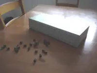
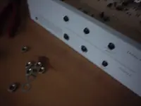
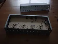
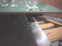
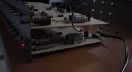
the power input on my rackmounted equalizer has come loose. so I am going to open it up and glue it back in place or something. I took all of the screws out, and i think there are 2 possible ways of opening it, but I am not sure which to do. On the bottom I can slide off a panel, which reveals the board. On the top I can slide off another panel, which is attached to the front faceplate and all of the knobs.

So, I am unsure of whether I should remove the board, to get inside, or the ouside plate with the knobs. I don't want to break it.

Thanks for any input.
 
FALKEN said:
so I am going to open it up and glue it back in place or something. I don't want to break it.
If you don't want to break it, let a repair tech handle it. If all you can say is 'glue it back in place or something' you may wind up using a corrosive glue that will eat your circuit board and make that unit into a paperweight that looks like a rack mounted EQ.
 
Certainly taking it to a professional is the best choice. If however you do decide to do it your self, go in from the top. They really aren't any simple repairs that involve removing the circuit board. Taking the faceplate off is typically not something too drastic.
 
I can help you take it apart, it's putting it back together that is the problem
 
just start unscrewing things and remember where it all goes. This stuff isn't as fragile as everyone likes to believe. That doesn't mean you can let your guard down, but take care and it will be okay. You might have to pull the knobs off the front panel (they should just pull off unless there is a screw in the side, but if you don't see a screw, just pull) and then use wrench or whatnot to get the hex nuts off. Then it would all come apart.

How much was this EQ becuase taking it to a tech is going to run a lot of money because most of them realize that people see these things as untouchable works of modern techniology that need expertise to even look at, let along do something as simple as tighten a screw on the inside of it.

There should be screws holding the power cord plug to the chasis. If not, then you might want to get some JB Weld because most glue isn't gonna hold somehting that has a power cord getting rammed into it.
 
it was maybe 100 or 150 bucks. 2 channel 4 band parametric so that is 24 knobs to pull off.. then remove the cover?

it has a power supply on the removable power cable, it is simply the input jack that has come loose. I figured it came loose because it was glued-on originally...maybe not?
 
FALKEN said:
it was maybe 100 or 150 bucks. 2 channel 4 band parametric so that is 24 knobs to pull off.. then remove the cover?

it has a power supply on the removable power cable, it is simply the input jack that has come loose. I figured it came loose because it was glued-on originally...maybe not?

Oh, its the input jack that is loose? The 1/4" input jack? Yikes! That could be a serious problem.

If there isn't just a hex nut that can be tighted to solve the problem, it is probably mounted to the circuit board. It would be worth it IMO to pull all 24 knobs off if thats what it takes to get inside and take a peek.

When you get in there, take some pictures and let us see if you can't figure it out on your own.
 
I can't remember ever seeing a piece of equipment that had a jack, a recepticle, or a pot that was glued on. Most likely a screw just came loose. If it had actually lost a nut or something (inside it of course) you should hear it floating around inside the unit.
 
Outlaws said:
Oh, its the input jack that is loose? The 1/4" input jack? Yikes! That could be a serious problem.

If there isn't just a hex nut that can be tighted to solve the problem, it is probably mounted to the circuit board. It would be worth it IMO to pull all 24 knobs off if thats what it takes to get inside and take a peek.

When you get in there, take some pictures and let us see if you can't figure it out on your own.
Dude, it's the POWER plug.

If you don't see screws on either side of it (or holes where the screws might have been) then there is a retainer clip on the inside. Just take off the knobs, you won't hurt anything. Taking the circuit board out from the bottom will be a much bigger pain and might require you to take the knobs off anyway.
 
no,no. it is the power input jack. which is very small. one of those small circular ones with a pin. I will give the knobs thing a try.
 
Farview said:
Taking the circuit board out from the bottom will be a much bigger pain and might require you to take the knobs off anyway.

thanks man!!! that is what i needed to know.

i'll take pictures and let you all know what happens.
 
It's always a good idea to take pictures AS you disassemble. I reach for the digital camera whenever I pull apart anything that's not straight forward... saved my ass a few times...
 
Isn't anybody going to ask *what eq* is being disassembled? :confused:

And I second the suggestion of taking digital pictures every step of the way! Notes written on a piece of paper will also be helpful. Finally, it's also useful to set out the pieces in the order in which they are removed, or laid out in some way that visually corresponds with how it all goes back together again.
 
SonicAlbert said:
Isn't anybody going to ask *what eq* is being disassembled? :confused:

And I second the suggestion of taking digital pictures every step of the way! Notes written on a piece of paper will also be helpful. Finally, it's also useful to set out the pieces in the order in which they are removed, or laid out in some way that visually corresponds with how it all goes back together again.

A digital camera can be such a time-saver.

I use ice cube trays for screws, labelling each compartment as I go. Top, bottom, input jacks, etc. I also number ribbon cables with a sharpie.
 
I followed everyones advice and pulled all of the knobs off, and then the cover. this revealed ANOTHER circuit board, and ANOTHER faceplate underneath. There were four screws on that faceplate, after unscrewing them, the sides-rear panel could be removed, leaving a faceplate with 2 boards attached paralell. So I got it open.
 

Attachments

  • DSC01017 copy.webp
    DSC01017 copy.webp
    72.6 KB · Views: 35
  • DSC01018 copy.webp
    DSC01018 copy.webp
    88.1 KB · Views: 28
  • DSC01022 copy.webp
    DSC01022 copy.webp
    78.2 KB · Views: 26
  • DSC01020 copy.webp
    DSC01020 copy.webp
    55.4 KB · Views: 26
  • DSC01023 copy.webp
    DSC01023 copy.webp
    96.4 KB · Views: 24
Below is the power jack input. It is attached to the board via those three points on the reverse side. it then has 2 feet that stick through two tiny holes. which is what came loose. Suprisingly, they just popped back into the holes.

Plugged it in, still works. So nothing needs to be re-soldiered. Just set back in place. The power input is not attached well and will come loose very very easily. I need a way to secure it to the board. Any ideas??
 

Attachments

  • DSC01026 copy.webp
    DSC01026 copy.webp
    77.1 KB · Views: 33
  • DSC01033 copy.webp
    DSC01033 copy.webp
    85.2 KB · Views: 26
  • DSC01034 copy.webp
    DSC01034 copy.webp
    77.6 KB · Views: 22
  • DSC01035 copy.webp
    DSC01035 copy.webp
    88.3 KB · Views: 25
  • DSC01028 copy.webp
    DSC01028 copy.webp
    75.1 KB · Views: 26
See....wasn't so bad was it?

Notice the "groups" on the circuit board? Simple stuff really. Basically probably the same thing repeated over with a different value or two to adjust a different frequency. I didn't realize it was a DC adaptor plug in. I was thinking of the three prong.

So explain again how it was mounted if it wasn't soldered and there was no screws? I think I missed it.
 
it looks like there are 3 soldiered points, and 2 sort of "feet" that stick into the two holes there. they just stick there. only they dont stick there anymore. the soldiered points also seem to carry the power, and they are still connected. I really think some glue would do it.


edit-
..actually I could just soldier the plastic to the board, where there are no lines or connections...I have never soldiered a board but I think this might do the trick?
 
Last edited:
Back
Top