Eliminating noise from RCA patchbay setup

Jzoha18

Member
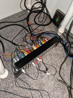
So I got 2 fostex model 3010 and 1 tascam PB32R to help interface 3 different multitrack machines with one Mackie CR1604 and my mixdown deck as well as have all my synths permanently wired. I figured since all the decks are running unbalanced RCA to the mixer without noise just fine I'd be able to get away with wiring everything and using little generic RCA patch cords to speed up and tidy up the recording process. Well I was wrong. Unfortunately this had introduced enough buzzing to annoy me. I'm here to ask if it's possible to eliminate it or if I simply am approaching this stupidly and should just get a regular 1/4 TS patchbay and cables. I have everything coming off power strips connected to one outlet. Seperated power cords as much as possible but still a good amount of buzzing. Will attach photos. Any ideas appreciated. The setup is patched correctly but simply is noiseyPXL_20210804_073217033.jpg
 
The hum doesn’t come from proximity of power cords to signal. It is probably a ground loop problem, or 0V reference differential between devices. It’s also not an issue with RCA vs TS. You’ll have the exact same problem because it’s still the same connections, just a different plug style. I would start by, one at a time, disconnecting a device from the patchbay array to see if the hum reduces or disappears. Reconnect the device if no change. See if you can identify if it is one device contributing. It gets complicated because there’s no standard to how signal ground is handled. If signal ground is bonded to the chassis of any device, and then that signal ground is interfacing signal ground on another device that has a floating ground chassis, that creates a massive ground loop. You can’t just plug all the devices into one outlet or circuit and expect it to work. We should have a standard so it does work, but we don’t. Do some of your devices have two prong power plugs and some 3 prong?
 
The hum doesn’t come from proximity of power cords to signal. It is probably a ground loop problem, or 0V reference differential between devices. It’s also not an issue with RCA vs TS. You’ll have the exact same problem because it’s still the same connections, just a different plug style. I would start by, one at a time, disconnecting a device from the patchbay array to see if the hum reduces or disappears. Reconnect the device if no change. See if you can identify if it is one device contributing. It gets complicated because there’s no standard to how signal ground is handled. If signal ground is bonded to the chassis of any device, and then that signal ground is interfacing signal ground on another device that has a floating ground chassis, that creates a massive ground loop. You can’t just plug all
the devices into one outlet or circuit and expect it to work. We should have a standard so it does work, but we don’t. Do some of your devices have two prong power plugs and some 3 prong?
Yes my mixer and otari have 3 but the mixdown deck and fostex deck and Yamaha 8 track are 2 prong
 
I agreehttps://www.amazon.co.uk/AV-Link-Ground-Loop-Isolator/dp/B000NVWB9O/ref=sr_1_5?adgrpid=58890497451&dchild=1&gclid=EAIaIQobChMIx7Sghuic8gIVp-jtCh2qSQKDEAAYAiAAEgKacfD_BwE&hvadid=259008422064&hvdev=c&hvlocphy=1006656&hvnetw=g&hvqmt=e&hvrand=10822293067374250747&hvtargid=kwd-294747876947&hydadcr=5082_1827834&keywords=ground+loop+isolator&qid=1628267229&sr=8-5, most likely a ground loop. I suggest one of these: (buggered that a bit but YSWIM?)

Yes, very cheap and therefore not of the highest fidelity (but actually not at all bad at neg 10 levels!) Look upon it as a 'diagnostic aid. While you are at it, sort the rat's nest out! How TF you can trace a signal banjaxes me!

Once you have identified the offending device you can either buy a better isolator e.g. an Art Cleanbox ll or try the 'OC shield one end' trick.

Just thought. Does the patch bay isolate individual RCA outers and those from the chassis? If not you could be on a hiding to nothing. If the chassis IS floating, take it back to a mains earth, NOT an audio ground.

Dave. https://www.amazon.co.uk/AV-Link-Gr...ds=ground+loop+isolator&qid=1628267229&sr=8-5


Dave
Thanks for the reply Dave. The patchbays are actually all labeled on the front it's so messy because I'm running 2 8 tracks. A 4 track and 16 mixer inputs and 8 direct outs. How would I be able to figure out if the fostex and tascam patchbays are floating? Schematic?
 
"How would I be able to figure out if the fostex and tascam patchbays are floating? Schematic?" Yes, a schematic would probably show the earthing arrangements but the easiest way is with a digital test meter and check for NO continuity between RCA outers. I have never handled an RCA patch bay so I don't know how it is built but to my mind, not only would each socket be isolated but they all but one pair would be isolated from the chassis and THAT pair taken to a known earthed piece of kit.
However, I doubt this is the case because it would make construction more expensive.

Tricky!

Dave.
 
I have managed to find a user manual for the Tascam PB-32 bay and it consists of two channel RCA 'modules' which would appear to be isolated from each other and chassis. In one position the modules can be 'half normalled' which is the most common configuration for patch bays I would say.

Dave.
 
I have managed to find a user manual for the Tascam PB-32 bay and it consists of two channel RCA 'modules' which would appear to be isolated from each other and chassis. In one position the modules can be 'half normalled' which is the most common configuration for patch bays I would say.

Dave.
So should I take a continuity meter to each socket or wait on my noise filter and just start testing each device. I'll say the tape returns into the 8 channels on my mixer that one of the patchbays is setup for by default is noiseless.
 
"How would I be able to figure out if the fostex and tascam patchbays are floating? Schematic?" Yes, a schematic would probably show the earthing arrangements but the easiest way is with a digital test meter and check for NO continuity between RCA outers. I have never handled an RCA patch bay so I don't know how it is built but to my mind, not only would each socket be isolated but they all but one pair would be isolated from the chassis and THAT pair taken to a known earthed piece of kit.
However, I doubt this is the case because it would make construction more expensive.

Tricky!

Dave
It appears i only have continuity between top and bottom RCA connections which would be the case for the half normalled config these bays are set up with. going to continue tracking and start unplugging everything but the deck and mixer and monitors and see what happens. The noise filter arrives in a day
 
Half or full normal is going to register continuity between upper and lower pairs of jacks. What you are looking for is to see if the signal ground is bussed on the patchbay (all jacks’ shield connections are tied together) or if they are isolated to each pair of upper and lower jacks. You checked both the signal conductor pin as well as the shield/signal ground conductor of the patchbay jacks, yes? And the upper and lower jack pairs are totally isolated to each other from the rest of the pairs? In your case that is probably best if that’s the case.

People do all sorts of things to deal with ground loop hum or improper system grounding resulting in noise induction…lift grounds, buy devices like noise filters, strap a small value cap in series with ground connections…I get it…sometimes you do what you have to do when it’s too hairy. I hope the noise filter works. But all of that is a band aid fix to either a design flaw in a device or an inconsistency in the application of signal ground theory between different devices in your array.

The bottom line is this:

If each device in your array of devices handles signal ground in the same way, and if each device’s ground plane is strapped to each other through a single path in order to eliminate any voltage differential between each device, and if each device has a proper ground scheme that doesn’t include any internal ground loops that induce noise, then hum and environmental noise induction should not be a problem. With a lot of help I completely reworked multiple facets of the ground scheme on a Soundtracs console I used to have. It was pretty jacked up all around. I had an AM radio station down the street and you could hear it loud and clear in every pathway. When the redesign was done, nothing…wonderful silence. I could even put my cell phone on a live call and set it right on the master section and open up every output and there was not one inkling of data chatter.

The big fat PITA is that it can be a major puzzle to investigate how each device’s manufacturer handled signal and chassis grounding (if signal ground references chassis ground…if the signal ground floats relative to the chassis we don’t care so much about the chassis, but then we have to pay attention to how the chassis references the building ground relative to the other devices in the array…and if the chassis floats also then there’s the potential safety issue…it’s all unfortunately complicated), and then beyond that another helping of PITA to get everything to align. Most the time we plug everything up, twist the key and hope it’s okay. Sometimes we twist the key and go “aw man wth…” Like you.

Most devices I’ve encountered are okay out of the box. But for me it’s part of getting to know a new device that enters my realm to open it up as soon as possible and look and see how they did it. Which usually also involves cross-referencing the schematics. But it is essential to look at the physical device to see how they handled signal grounding, and then the next step is to look for bad design issues that result in internal ground loops. What I’m going for is that each input and output jacks’ signal ground bonds to the chassis as close as possible to the jack, and that there is good positive bonding of the audio path 0V reference to the chassis, and then that the chassis is bonded to building ground through only one path. This avoids ground loops, offers a very low resistance path to ground for any noise, and ensures each device in the array is referencing the same ground reference through only one path. Again, most the time I open up a device to take a look and end up saying “good” or at least “that’ll work”, but in some cases I’m like “what were they thinking…” My Soundtracs MX-32 mixing console was a good example. But I think doing all that and knowing what to look for is understandably beyond most people and it’s only not so much for me because A. I’ve had some really nice smart people help me through some pretty exhaustive projects to correct issues, and B. I’ve studied the issue relative to my own array of gear and have enough of a grip on how things need to be to avoid the headaches. I’ve studied and had people teach me relative to a need to fix a problem. So I know what to look for now. It shouldn’t be so complicated. Manufacturers should be interested in making it simple for the end user. I think things have improved with time, but for those of us using devices manufactured across many decades, we are at risk of running into greater inconsistencies the further back in time we go with what gear we’re using.

For you, knowing you can connect a few fundamental devices and things are okay is a great start. And then from there do the add one thing in at a time until things go to pot and post some detail of what device it is, how it’s inputs and outputs are connected to other devices in your setup, like what devices and what type of connections, where and how the device is mounted, and what type of power connector it has.
 
T
Half or full normal is going to register continuity between upper and lower pairs of jacks. What you are looking for is to see if the signal ground is bussed on the patchbay (all jacks’ shield connections are tied together) or if they are isolated to each pair of upper and lower jacks. You checked both the signal conductor pin as well as the shield/signal ground conductor of the patchbay jacks, yes? And the upper and lower jack pairs are totally isolated to each other from the rest of the pairs? In your case that is probably best if that’s the case.

People do all sorts of things to deal with ground loop hum or improper system grounding resulting in noise induction…lift grounds, buy devices like noise filters, strap a small value cap in series with ground connections…I get it…sometimes you do what you have to do when it’s too hairy. I hope the noise filter works. But all of that is a band aid fix to either a design flaw in a device or an inconsistency in the application of signal ground theory between different devices in your array.

The bottom line is this:

If each device in your array of devices handles signal ground in the same way, and if each device’s ground plane is strapped to each other through a single path in order to eliminate any voltage differential between each device, and if each device has a proper ground scheme that doesn’t include any internal ground loops that induce noise, then hum and environmental noise induction should not be a problem. With a lot of help I completely reworked multiple facets of the ground scheme on a Soundtracs console I used to have. It was pretty jacked up all around. I had an AM radio station down the street and you could hear it loud and clear in every pathway. When the redesign was done, nothing…wonderful silence. I could even put my cell phone on a live call and set it right on the master section and open up every output and there was not one inkling of data chatter.

The big fat PITA is that it can be a major puzzle to investigate how each device’s manufacturer handled signal and chassis grounding (if signal ground references chassis ground…if the signal ground floats relative to the chassis we don’t care so much about the chassis, but then we have to pay attention to how the chassis references the building ground relative to the other devices in the array…and if the chassis floats also then there’s the potential safety issue…it’s all unfortunately complicated), and then beyond that another helping of PITA to get everything to align. Most the time we plug everything up, twist the key and hope it’s okay. Sometimes we twist the key and go “aw man wth…” Like you.

Most devices I’ve encountered are okay out of the box. But for me it’s part of getting to know a new device that enters my realm to open it up as soon as possible and look and see how they did it. Which usually also involves cross-referencing the schematics. But it is essential to look at the physical device to see how they handled signal grounding, and then the next step is to look for bad design issues that result in internal ground loops. What I’m going for is that each input and output jacks’ signal ground bonds to the chassis as close as possible to the jack, and that there is good positive bonding of the audio path 0V reference to the chassis, and then that the chassis is bonded to building ground through only one path. This avoids ground loops, offers a very low resistance path to ground for any noise, and ensures each device in the array is referencing the same ground reference through only one path. Again, most the time I open up a device to take a look and end up saying “good” or at least “that’ll work”, but in some cases I’m like “what were they thinking…” My Soundtracs MX-32 mixing console was a good example. But I think doing all that and knowing what to look for is understandably beyond most people and it’s only not so much for me because A. I’ve had some really nice smart people help me through some pretty exhaustive projects to correct issues, and B. I’ve studied the issue relative to my own array of gear and have enough of a grip on how things need to be to avoid the headaches. I’ve studied and had people teach me relative to a need to fix a problem. So I know what to look for now. It shouldn’t be so complicated. Manufacturers should be interested in making it simple for the end user. I think things have improved with time, but for those of us using devices manufactured across many decades, we are at risk of running into greater inconsistencies the further back in time we go with what gear we’re using.

For you, knowing you can connect a few fundamental devices and things are okay is a great start. And then from there do the add one thing in at a time until things go to pot and post some detail of what device it is, how it’s inputs and outputs are connected to other devices in your setup, like what devices and what type of connections, where and how the device is mounted, and what type of power connector it has.
Thanks again for such a good reply! i unplugged everything that wasnt simply the mackie CR1604 I/Os and the tape deck (right now its a 424mk3 as the yamaha mt8x i had patched up was acting up DROPOUTS AFTER A FULL SONG IS DONE SO ENRAGING!!!!! >:(>:(>:() anyways imgoing to trouble shoot more with the noise filter monday and mess with the meter more as well.The Yamaha is currently sitting with cailkleen rbr on its roller as after a full cleaning and degaussing the dropouts didnt stop. TDK SA60 and maxell XLii bothhaving dropouts. very frustrating as the deck was basically near mint in box but the rollerlooked like it had never been cleaned and quite a bit of junk came off of it so im hoping the roller was the reason. sorry for the ranti had this patchbay making noise and my deck having dropouts all in one weekend LOL. Ill keep you updated on the patchbay!
 
I’m sure that’s really frustrating. I have totally been there and will be there again.

Which tracks are dropping out on the Yamaha? It takes practically a microscopic bit of debris or buildup, like literally, to bring a track to almost or even completely nil, on a cassette 8-track…even cassette 4-track, or 1/4” 8-track (those are about the same track width).
 
Ok so i made a discovery testing this all out. Sadly im running a hosa TS to RCA into a RCA to RCA Female to Female adapter with a generic RCA lead into a patchbay and this creates noise. i unplug the leads to the mixer and deck and directly connect them to the instrument and still noise. i plug the instrument directly into the mixer with a RCA to RCA to RTS with the rest of the connections through the patch bay and still noise directly from the instrument into the mixer. i swap the generic rca to adapter to rca to TS with just a TS cable and the noise is gone. basically i think these shitty cheap RCA cables are causing the noise. are those regular cheap chinese RCA cables prone to buzzing? Could it be from the resistance between a instrument type cable and a tiny RCA cable? idk but i can by pass the patchbay as the input with the weird RCA adapter rig cable and just go through the mixer itself and the noise is present but using a normal TS to TS makes it go away and the rest of the patchbay is not introducing noise when i move the tape return faders up.
 
Wait…you’re connecting an “instrument” through the patchbay, like a passive electric guitar or bass? If that’s the case I wouldn’t do that. That should connect directly to the instrument preamp using a good quality instrument cable.

And not all cables are created equal. Not even close. You get what you pay for. The shielding in the cheap RCA to RCA cables may be inadequate or missing altogether. Using adapters/problem solvers is fine in a pinch. I have a small tackle box full of them. But they should never be permanent. Buy or make the cables or snake you need in order to make the most direct connections possible, and if unbalanced keep the cables as short as you can. 25’ total is kind of the extreme limit, I try to keep unbalanced cable runs less than 10’…shorter is better.
I meant a line level synthesizer. so could you recommend proper RCA to RCA patch cables that arent going to create this buzzing? like quality ones? it seems that these cheapo cables are why i noticed the HOSA TS to RCA does not do this when its connected to the patchbay
 
Last edited:
I’m sure that’s really frustrating. I have totally been there and will be there again.

Which tracks are dropping out on the Yamaha? It takes practically a microscopic bit of debris or buildup, like literally, to bring a track to almost or even completely nil, on a cassette 8-track…even cassette 4-track, or 1/4” 8-track (those are about the same track width).
It would fluctuate from channel 1 or 8 sometimes the entire first four channels or more. I got it to transfer a mix properly after a degauss and hitting the pinch roller with some cailkleen rbr. I think the reason this happened was that the mt8x has tape scrapers on each side of the playback/record head that built up some gunk and I didn't clean it in the past 4-5 months of use. The roller wasn't cleaned either. I blew out some residual gunk with air and scrubbed everything and it should be fine
 
so using the ground loop isolator seems to be creating way more noise. where exactly should it be patched in? I have a line level source with noise FYI
 
I wish I could help. I’ve never used one of those things. What is that you have actually? Like brand, model, link to a manual?
 
And rewind for a second…you were saying things were nice and quiet and I suggested you plug one thing in at a time until there’s a problem. So did you do that? And what device is it that is making the offending noise?
 
Back
Top