T
TaperChuck
New member
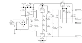
Minion said:Here is the design I am useing ,It is basicly the datasheet design with a Basic ballanced line driver at the output to create a ballanced output....I am also useing 10K Reverse Log taper pots for Gain Controll.....
In my design I am not useing a OPA137 for DC offset but a Dual TL072 which are much cheaper and I am useing a Dual opamp because it does the DC Offset for 2 Channels..... I have allready designed the 2 channel PCB and etched a couple PCB"s and I am just waiting for some Parts to show up before stuffing the Boards......
Cheers
Let us know how that works. I have aquired a bunch of parts to make the same basic design. But, I really need a microphone pre-amp I can use that runs on 12v DC, in the field. I don't know enough about electronics design to engineer a 12v power supply that will work with the INA217.
")


")