Audio Technica AT-RMX64 Story…

  • Thread starter Thread starter sweetbeats
  • Start date Start date
@Mark7

2CF797E2-A6D4-4E26-8727-1DCCDFCEB602.webp
 
as always youre the man
Let there be light…

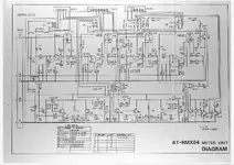
View attachment 128385

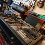
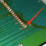
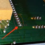
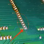
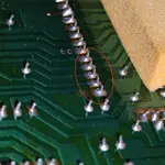
Yes…got the meter lamps replaced which, thanks to 
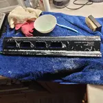
@famous beagle ‘s tutorial on the subject elsewhere on this very forum (just do a search for threads started by him with AT-RMX64 in the title and you’ll find it…), was a breeze…I’m polishing the meter bridge metalwork, and still need to clean all the knob and switch caps, but then I’ll put it back together and call it “done.”

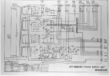
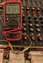
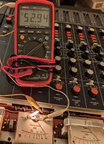
I’ve been working on other things and also manhandling daily life, but I did do a bunch of other general investigative work into the guts of the AT-RMX64 because, unfortunately, I think until a miracle surfaces, I’ve lost all hope of obtaining tech docs for this thing…and I think with help from friends I’ve done a yeoman’s job trying. I wish the buyer of the full-size schematic set on eBay a couple three years ago would see this and do the AT-RMX64 community a solid, but that’s probably not happening…or Michael Dewenter of transanalog.com would respond…I’ve sent many emails through his website at this point with no response, and three years ago when I did connect with him via email he confirmed he had the documents, but had just moved and didn’t have his scanning equipment or documents available…totally respect that. But it’s been crickets since. So we know the documents are out there, but nobody is helping. I didn’t share this earlier but I have a good friend who has been in electronics for decades, super smart, worked for Tapco and Mackie among other companies designing consoles, still does quality sound reinforcement engineering to this day…connected…turns out he knows somebody at AT America that remembers the AT-RMX64 and was willing to go fishing…dead end. SO…I said fuck it and took to reverse engineering.

I have a complete electrolytic cap list by PCB with audio path caps identified for anybody that feels they need to recap. It will help you with your shopping. It also calls out differences between early generation and late generation AT-RMX64s, because there are some differences (limited) in the caps…

I also have almost every pin of the input modules mapped, and many of the sub modules…I figured out the signal flow through the record, bias and playback amplifier PCBs in the transport section.

I’m really busy so I haven’t put any thought to how to disseminate this information, but if you need it hit me up…I basically spent a big chunk of quality time mapping it out.

If nobody helps you, you have to help yourself.

Anyway, that’s the update. I’m on the cusp of having a fully operational 9/10 condition AT-RMX64 and have a butt-load of guts-knowledge now to support the device.

OH…and I think the main difference between the early and late generation units is a 555 IC timer circuit for muting when arming tracks. I should capture a video of the muting action on mine, but basically on the Mother C Unit of the later generation machines, which is the motherboard under the back connector of the SUB modules and the transport cards, there is an added 555 IC timing circuit, and related circuitry on the record amp PCB and SUB modules that mutes all output from any armed channels when you make changes to the track arming. That means there are differences in the record amp unit, mother C unit and SUB modules between early and late machines…not compatible. Test it…put in a cassette, send some signal to all 4 sub modules, arm all 4 tracks and turn up the record level…set all the meters to TAPE…put the transport in REC-PAUSE. You should now see level on the 4 meters. Take one track out of armed status. When you do this on a late generation machine, all tracks should go dead level-wise for a second or so, and then pop back. That’s the timer muting circuit working. I believe if you do this on an early machine you won’t see the muting action, and may hear switching artifacts in the outputs if monitoring. No big deal, and honestly it speaks to the relative fancy nature of the project that is the AT-RMX64 that they took the time to do this midstream in production, but it’s good for folks to be aware of. IMO I don’t think it makes late gen better than early gen, it still the same signal path and transport, etc., but it DOES mean incompatibilities in some of the PCB assemblies.

Okay.

That’s all for n
 
So it’s been awhile since I’ve updated this thread. But I am nearly uncontainably excited about the reason for this update. You see, it would seem the greatest Achilles heel of the AT-RMX64, the lack of available technical/service documentation, is in process of exoneration.

I always had this hope, after all my failed attempts to track down said documentation, *somebody* out “there” had to have the documents, and would see my threads/online conversations or YouTube videos on the AT-RMX64, and would, figuratively speaking, stand up and say “I’ve got them…allow me to help.” Yes I’ve been told I’m an incurable idealist. BUT…it seems that’s exactly what’s happened. A member here, @oddiosmith, has the documentation, some 150 pages of schematics, board layouts, parts lists and service instructions, for the AT-RMX64, and is currently process of painstakingly converting them to digital format. If I understand correctly oddiosmith is an “OG” AT-RMX64 owner dating back to its inception in the mid-1980s, and was working through addressing some issues with the unit and found my YouTube videos, and, furthermore, having found them helpful, was led to membership here and this thread. Long story short oddiosmith has stood up and said (not literally) “I’ve got them…allow me to help.”

At some point in the not too distant future there will be a complete and orderly good quality scan of the entire document set to be openly shared. Please stay tuned. I consider this to be, at long last, the coming coronation of sorts for the king of self-contained Philips Compact Cassette format 4-track multitrack production devices. In the meantime, here’s a practical and helpful teaser…a two-page excerpt of type-written instructions for the calibration and electronic setup of the AT-RMX64. Note the excerpt does not include meter calibration instructions, which should be the very first step. I have a YouTube video demonstrating the meter calibration process. So if you’re going to engage the instructions below start with meter calibration. Also, disclaimer, proceed at your own risk, I am not saying you *should* proceed, but rather only sharing information. You are responsible for your own safety and the well-being of your equipment. That said, check out the attachments. Amazing! Thank you @oddiosmith!!!
 

Attachments

Kudos @sweetbeats & @famous beagle for providing all this info. Your help is vital guys.
Recently acquired one of this beasts.
Now I'm not that guru guy when it comes to "tapeheads" stuff but I have a little experience by repairing my Revox A77 & Fostex A8 r2r machines.

It was in good condition (transport control buttons almost intact), some cosmetic wear & tear.
It appears to have the common issues a similar to @sweetbeats's case.

CH2 VU lamp is off.
Two input channels with intermittent signal. ---One it passes no signal at all.
Common transport difficulty, Play function barely works, RW/FF don't.

After a good cleaning, IPAlcohol for every pinhead connector some issues gone.
I just got it in my bench, it'll be a slow repair as other things are currently running too.
I'll keep you up with repair progress.

1. For the moment, there's smthng that bothers me. The unit is a USA mains one, 120V 50/60Hz labeled. I'm based in EU, 230V.
I'm currently using a step down power trafo, rated 100W. Have checked volts / rails etc everything is fine.
It runs ok for now, but as I'm planning to keep the thing, will it be safe in the long run?
Furthermore, the PT I'm currently using makes the common buzz laminations mechanical noise by the time I bought it, not now.
Don't know if this is a good thing. It's not the best quality step adapter trafo out there but not ultra cheap / chinese. EU brand, 40 bucks price range. I can eliminate the noise by loosen/tighten laminations/bell screws but it's not permanent fix. After an hour or so it starts to vibrate again and I'm in playing with screws again.

2. Now that we have the SM, it's verified that the VU lamps are 8V rated (point 4 calls for +8V) but, can anyone tell the mA current according to diagram? If you trace point 4 (+8V rail) back to Power Supply diagram, at 7815 regulator's output, is this a "0.4A" 400mA, (goes to points 2&4) so let's say 200mA for point4, 50mA for each meter? Don't know if makes sense though.
 

Attachments

  • IMG_20250524_111230.webp
    IMG_20250524_111230.webp
    648.8 KB · Views: 146
  • IMG_20250524_110233.webp
    IMG_20250524_110233.webp
    432.8 KB · Views: 149
  • IMG_20250522_085330.webp
    IMG_20250522_085330.webp
    733.4 KB · Views: 143
  • IMG_20250521_055050.webp
    IMG_20250521_055050.webp
    1.5 MB · Views: 157
  • Screenshot_2025-05-24-11-00-18-655_cn.wps.moffice_eng-edit.webp
    Screenshot_2025-05-24-11-00-18-655_cn.wps.moffice_eng-edit.webp
    132.8 KB · Views: 147
  • Screenshot_2025-05-24-10-43-43-008_cn.wps.moffice_eng-edit.webp
    Screenshot_2025-05-24-10-43-43-008_cn.wps.moffice_eng-edit.webp
    136.2 KB · Views: 143
Last edited:
1. The AT-RMX64’s rated power requirement is 65W, so I see no reason why a 100W rated step-down power transformer wouldn’t be fine. If the mechanical noise bothers you you can always eventually look for something higher quality.

2. The lamps I used in my AT-RMX64 are JKL DA-403. These are 10,000 hour rated 6.3V 70mA…that’s 0.441VA. That’s the same as an 8V 55mA rated lamp. So anything around that is fine. 8V 100mA is another common one. It I think 8V 55mA is the most common I see. JKL DA-503 is that spec.
 
2. I can source 9V 50mA from local radio shack. It'll be fine I guess right?

About intermittent input channels: 4 of 6 are passing signal only if I move them a bit to the left (while not being screwed down so I can move'em) even after IPA/ deoxit cleaning and reflow solder. When they're straight (and screwed in place) no signal again.
Could it be wise if I'd bend the pinheads up a bit all at once using pliers? Any ideas other than replacing those pinhead connectors?
 
9V 50mA is 0.45VA. That’s almost identical to the two examples I gave you. Should be fine.

I would not bend pins. You reflowed solder joints in both the motherboard and input modules? Did you maturely exercise the connections or just clean them, apply the DeoxIT and then reseat? Which DeoxIT are you using? I can’t recall the pitch on those connectors…but it’s something standard and u don’t think it would be difficult to source new sockets and right-angle on headers and replace them. I just found after cleaning the connections and exercising them they were reliable again.
 
Didn't reflow solder joints in motherboard yet. Will do today, was my next plan. Just cleaned with IPA 99.9 (I'm pharmacist so I have full access to chemicals). Here in EU all we can get is contact cleaner with or without oil. Kontact and Teslanol brands mostly. Oil free contact cleaner is basically IPA. So I either use pure IPA for contacts or Teslanol T6/Kontakt 60 for "radio use" pots,faders,switches etc. Do you think I have to use the last ones (something with oil)? What deoxit did you use D5 or F5?
 
Never ever use a contact cleaner with lubricant on metal-to-metal contacts, either connectors or switches…so I would never use F5 on things like cardedge connectors. F5 is specifically for carbon element potentiometers. IPA is great for cleaning up dirt and debris, but it doesn’t treat and protect the metal surfaces. It’s also difficult to get it down into small sockets like found on the cardedge connectors on the AT-RMX64 (vs in a spray can). So if your measures so far were to wipe the pins with IPA on the input modules and reflow those solder joints, I’m not surprised you’re still having trouble. I use DeoxIT D5, hose down the pins and sockets, exercise the connections (plug and unplug 10-20 times) spray everything off with compressed air (especially important for clearing out the sockets), hose down with D5 again and exercise again, compressed air again, and then a light application of D5 and test.
 
Never ever use a contact cleaner with lubricant on metal-to-metal contacts, either connectors or switches
Yeap I know, I'm into repairs almost 30 years. Just misunderstood thought you said you used F5. 🙄

So, yesterday I removed bottom plate revealing the back of the motherboard just to notice that almost every female pinhead connector socket had cracks on one or more edge solder joints.
As u can see in the pics below the most prone to cracking joints were the edge ones.
Removing glue residue from those yellow sponges were PITA.
Resoldered fresh every solder joint of each connector there.
Boom. Mixer section in 100% working condition again.

Really like the sound & EQ of that thing.

Now only thing left is the transport section then calibration, final touches etc.
I'm waiting for idler tire replacement to arrive.
I will be back with future report.

Cheers.
 

Attachments

  • IMG_20250526_165312.webp
    IMG_20250526_165312.webp
    414.7 KB · Views: 158
  • IMG_20250526_165350.webp
    IMG_20250526_165350.webp
    379.3 KB · Views: 155
  • IMG_20250526_165438.webp
    IMG_20250526_165438.webp
    387.4 KB · Views: 147
  • IMG_20250526_165511.webp
    IMG_20250526_165511.webp
    399 KB · Views: 142
Just for the record. 8VDC, 53mA.
 

Attachments

  • IMG_20250528_035133.webp
    IMG_20250528_035133.webp
    544.6 KB · Views: 142
  • IMG_20250528_035146.webp
    IMG_20250528_035146.webp
    611.9 KB · Views: 149
Cool. Thanks for posting that. So any axial lead lamp with about a 0.44VA rating will be a close match to the factory lamp. “VA” in this case means volt-amp…that’s the voltage rating multiplied by the amperage rating. So 8V 55mA (0.055A) is 0.44VA. 6.3V 0.07A is about the same. 9V 0.05A is about the same. You can do the math. More or less is fine…more will typically be brighter. Less will typically be more dim.
 
Yes, 6.3V 70mA (your choice) is about the same but I think bulb will be more bright & shorter life.
9V 50mA (my choice) is in the same ballpark too, but I'd prefer if I could find locally a 9V 30-40mA.
I can source 12V 20 & 30mA locally (that would be the best bet concerning lifetime & consumption) but it'll be too dim.

Anyway, we're good to go with either 6.3/0.07 or 9/0.05 it's not the end of the world.
 
Back
Top