Apex 460 capacitor change?

  • Thread starter Thread starter EdgeGuy
  • Start date Start date
Removing the RF caps was one of the original mods as they act like low pass filters for transient highs.

Many actually remove all the inner screening but I reinstalled the fine screen as it increased plosives quite a bit and I didn't notice as much of a difference as others have. Changing the resistors and such opened things much more for me.

There were some changes that I tried that were written about that did raise the self noise significantly, but overall I'd say that the mic's are at least as they originally were, if not more so.

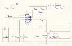
Most of these changes were inspired by the original C24/C12 and U47 schematics.

One thing I was wondering is what would the "optimum" voltage be for a 12A*7 tube?

The C12 used about 66v at the plate with 120v coming in at B+ according to one schematic I've come across.

Lucio
 
Removing the RF caps was one of the original mods as they act like low pass filters for transient highs.

If the cap values are too high, then use smaller caps before you just outright remove them. The corner frequency should be so far above audio it shouldn't matter.


One thing I was wondering is what would the "optimum" voltage be for a 12A*7 tube?

That's a complicated question. Read the 12AXY (or AT, whichever), especially the plate voltage vs. current chart with curves for various grid voltages. Here is an article that discusses how to set a tube's operating point:

http://diyparadise.com/tubeloadline/tubeloadlines.html

Thus it depends on the plate current you need, also headroom. A capsule buffer isn't going to need a ton of headroom, because the signal is fairly small to begin with. Some tube datasheets give you helpful curves on distortion with respect to plate voltages and current, but the datasheet I have on 12AX7 does not.
 
If the cap values are too high, then use smaller caps before you just outright remove them. The corner frequency should be so far above audio it shouldn't matter.

So if I put a .01uf/63v in place of the .1uf/63v do you think that this would raise it enough or maybe even a .001uf or would that put things too high to block RF?

Here is an article that discusses how to set a tube's operating point:

http://diyparadise.com/tubeloadline/tubeloadlines.html

Thus it depends on the plate current you need, also headroom. A capsule buffer isn't going to need a ton of headroom, because the signal is fairly small to begin with. Some tube datasheets give you helpful curves on distortion with respect to plate voltages and current, but the datasheet I have on 12AX7 does not.

Thanks for this, I'll research this more to get a better understanding. I appreciate it.

Lucio
 
So if I put a .01uf/63v in place of the .1uf/63v do you think that this would raise it enough or maybe even a .001uf or would that put things too high to block RF?

Wow, it was a 0.1uF? Yeah, that is way large. .001uF is more typical there.
 
mshilarious,

Would it be a problem to use .001uf/250v in place of the 63v?

I already have these higher voltage versions so I wouldn't have to make such a small order of parts.

Thanks,

Lucio
 
Jonk,

No this is about C9 and C10 which filter RF.

It was originally said to remove them because they act like a low pass filter cutting off the transient highs, but I think what mshilarious said makes alot of sense. This way you don't lose the highs but still filter out any RF interference.
 
Hey Phil,
Okay, finally getting around to trying your p.s. mods.

sorry to keep asking about the 3.3mfd cap after C6, but just to make absolutely sure, you mean, between C6 and R5 right?

I have a 2.2uF/250V wima that I can put there. Is the voltage rating going to be sufficient enough though?

And one more, when you say bypass the zeners with tants, do you mean just D5 and D6, or all of them?
(actually, I don't know whether the other diodes are zener or not, so that may be the answer to than question)
 
Bump.

Anybody know the answers to these questions? There's a number of caps in the mic that have the voltage around 250V, so I imagine it would be okay in the p.s. too? (for this cap that Phil is adding)
 
Bump.

Anybody know the answers to these questions? There's a number of caps in the mic that have the voltage around 250V, so I imagine it would be okay in the p.s. too? (for this cap that Phil is adding)

Can you post another link to the schematic? This thread has gotten kinda long to look through . . . :o
 
Regards Matti
 

Attachments

  • untitled.webp
    untitled.webp
    161.2 KB · Views: 424
Sorry, my bad! This then, the model number is misleading.
 

Attachments

  • 2.webp
    2.webp
    101.7 KB · Views: 408
A very interesting thread. Our band is looking for a good single mic live perfomance mic and have had the 460 recommended as a good option. In reading through this thread it would appear that by spending some extra $$$ a really good mic be had. I am a complete technopeasant in electronics and would appreciate it someone could itemize the changes that give the best bang for the buck
 
Hey guys,
Just bringing this one up again concerning the Phil Townsend power supply mod last page. I've contacted Phil a couple times but he hasn't gotten back to me.

Anyway, when he says that he's putting a cap (3.3uF) after C6, does he mean that one side of the 3.3uF is grounded and the other side connects to the circuit between the positive side of C6 and D11?

Or does he mean that one side of the 3.3uF connects to the positive leg of C6 and the other side to D11?

I'm thinking it's probably the former, but can someone who understands the power supply circuit confirm that?

It's the former. If you put a cap in series with your DC supply, it has a nasty habit of blocking the DC completely :eek:
 
First off, thanks to all you for sharing your expertise.
I'm a bit overwhelmed by the info on this mod I've read here, on the tape op board, on prodigy pro, on gearslutz and on studio forums. So if someone could kindly help me sort all this info I've read..... :confused::confused::confused:

here's my story so far:

I've already managed to install a peluso cek12 capsule in my 460. I definitely like it better than stock. And I've removed the screen door mesh from the basket (foolishly, i didn't do a before/after check).

Now I have a Cinemag 2480 i'm itching to install, so if i were to do the suggested steps below that I put in boldface (plus I'd have to cut the connection between pins 4 and 5 right?) would I end up with a reasonable good mic in you folks' opinions?


The C12 has quite elaborate tube biasing. One half of C24 is much simpler and resembles input stage of the 460.

The 460 schematics is the same as Nady 1050. I have posted about later somewhere here, analyzing why the designers were forced to use such... non-orthodox solutions and also posted listening impressions of the mod.

To make the circuit looking more like C24 is quite easy:
Remove R8
Cut traces from tube pins 6,7,8 and short them together
Connect C8 to juncion of pin 1 and R2
For the transformer use a high quality 1:8-1:10 Lundahl or Cinemag
(depending on your taste).

For upgrading, besides aforementioned C8:

Ceramic C4 replace with polystirene cap of the same value with at least 150V rating.
You also can experiment with removing local NFB C6 cap, or replacing it with Black Gate cap of the same value.

You could as well to get rid of C9-C10.

Also, someone suggested i buy a .68uf 250v mylar cap for C8 (which seems to run contrary to what a lot of you recommend). Since I have this part in hand (Phillips brand if that matters), do you think it would be an improvement over the stock electrolytic or should i just eat it and get a cap that would be more appropriate for half-of-a-c24-ish-type mic that this become?

Thanks in advance to anyone who can help clear things up in my mind!
 
Last edited:
Ok, first, install the cinemag 2480 transformer. Don't cut out/rewire anything else. Record something before/after this mod for reference. Now cut out C9-C10. They're just rf caps and the new transformer makes them pointless. At this point, removing the CF circuit you may/may not want to do. I didn't and I like the mic just the way it is now. I also have the CEK-12 capsule. Also, you need to put in a 6072a tube. That'll make a great difference as well. I had bad luck with some other 12ax7 types, not good sounding. I used an RCA NOS 6072a and it's awesome. The .68 mylar should sound a bit better than the stock electrolytic (less grainy).
At this point, not having done the CF mod, your mic should be better than almost anything you can get for 5X the price (better being subjective).
 
Let's see, use a .68uF cap that you already have, or spring $1.50 for a 1uF 250v that will give you extended low frequency?

That's entirely up to you.:)
 
Back
Top