briank
analog for the people!
Thankyou thankyou thankyou! I'll fiddle with it next I'm in the studio and report back-
Too far to drive....
Let us know what you are seeing on your scope and the settings for it if you get into trouble. In general use 10X if you can as that at 10X the probe has a higher impedance and thus loads the signal down less.
-Ethan
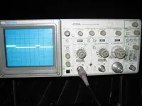
Odd looking trace....
Looking at your scope - Verticle mode should be set to "channel 1" not "both". In both the 2 channels can be added together (as set here), displayed one then the other (alternate) or a little bit of one displayed then a little of the other (chop) done quickly. Alt works well for fast horizontal times, chop for slower times.
Channel 1 is set for 10 volts per division which gives about 5 volts of signal (half a division) which is consistent with TTL logic levels.
Looks like the inner and outer rings of the horizontal time per division knobs are not locked together. They should be locked together unless you are using split timing modes.An advanced thing to do.... in over my head with oscope stuff ;D for special cases.
You have 2 "on" pulse widths. THis is odd to me. I would expect each pulse to be of equal width.
Not much else comes to mind at this time.
 and didn't see where the knobs locked together, guess that's a "gotcha"...I was advised above not to set to chop or alt so that's why that got set the way it did...in over my head with this oscope stuff
  will try again-

You can trace the takeup tach signal through IC 10, IC 8 and IC 9. Also follow take up torque signal through IC 12 and thus to the fet switch IC 25.
Then it says that if the tap spills in play you should suspect IC3 and IC7. IC7 is the one in question for the takeup side but I would leave that alone until you have eliminated oher things. These are the dividers.
First off you should have a look at fig 3-13 on page 3-17, as well as reading the play servo loop info in 3.4.2. I'm sure you have but this is where I started in thinking about it.
It basically says that the reel servo torque is set by the difference in the capstan speed and the reel speed. Moving over to 8.3 on page 8-4 it points out that because the difference in speed is calculated then the capstan signal must be right and if wrong can look like a bad analog board. (Check the capstan PLL waveforms for any problem)
The goal here is to look for anything that does not look right. The tach signal is a DC level that corrosponds to the takeup reel speed. you can rotate the takeup reel by hand and you shouuld see the level change at each place in the signal chain.
The fet switch selects which torque signal to send to the motor driver so you should be able to see the torque level before the FET switch even if the switch is off. IC 24 is the driver for the fet switch. Only one of the gates should be "on" and the others off.
You shouuld also be able to check the torque level at IC 26 and 27....
Hope this helps
--Ethan