T
The Ghost of FM
Banned
Nice restoration job, Cory! ")
Those last few pics clearly show that you are superior to Photoshop!
Cheers!
Those last few pics clearly show that you are superior to Photoshop!
Cheers!

Here's the deal...the "one more" task is to hold the record button and simultaneously hit PLAY to engage record mode. So yep, you've got to arm the track, switch the source and put the machine into record all at once.
"Sel Sync" hmm. I always thought the synchronization word meant that the
musical tracks would be in sync allowing one to play in time with the
previously-recorded tracks, which was the whole purpose of the system. I'll
get that the audio off those record heads sounded pretty bad. Even the AG
440 doesn't sound all that good in sync mode. the MM 1000 solved that
problem with sync playback sounded almost identical to the playback on the
play heads.
I wonder if Les ever got a newer machine? That old beast "The Octopuss" must
have been a pain to operate. Lots of getting up and down operating controls
and "punch-ins" were probably impossible due to punch in noises which weren't
eliminated until the MM 1000 came out. The 440 made thumps when put into
record and then there was the switching problem. We had to have a dedicated
person to operate the machine if we were going to attempt a punch in on a
440-8. He had to switch the record channel from sync to record ready, move
the monitor switch to Input and hit the record button all almost
simultaniously! The MM 1000 did it all automatically.
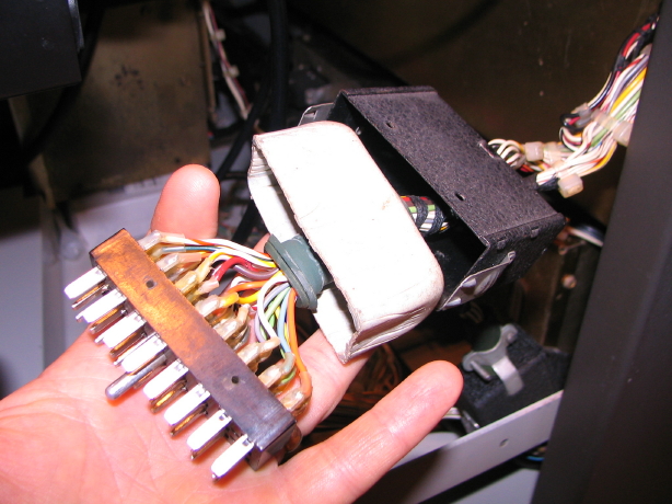
Now back to my record arming problem...the problem follows the cabling, so its NOT in the electronics...but...WHERE????????
Just on the electronics side.
I'm actually pretty excited because that's a pretty substantial clue...
") I want to get a snake mae up before I push it up to the wall to plug it up to the mixer, and get the tensions reset since those are set at the back of the machine. Then I can tuck back up to the wall, clean up my mess, recheck the brakes and then adjust the pinch roller tension and position and then....I get to start calibrating. Love the new avatar, seems fitting too!!
I want to get a snake mae up before I push it up to the wall to plug it up to the mixer, and get the tensions reset since those are set at the back of the machine. Then I can tuck back up to the wall, clean up my mess, recheck the brakes and then adjust the pinch roller tension and position and then....I get to start calibrating. Love the new avatar, seems fitting too!! Yeah, I decided it was time to upgrade the avatar. That one of the reel in motion was from years ago when I still had my Tascam 58. The 58 is long gone. I like my MM-1000. Avatar = ode to Matilda.
SO...
Thanks for the interest in what it was.
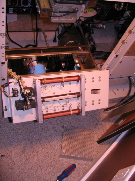
I chased down a couple other hunches to no avail, retraced my steps that led me to believe it was cabling but it wasn't totally adding up because the cabling tested good. I then remembered that I was going to bump the output of the +24V supply.
Remember that it was outputting about +22.5V under load.
I realize now that I refurbished that supply around in between the tracks all arming and then the onset of the track arming problem...recapped it, replaced the bridge rectifier as well as a zener on the regulator board...certainly that might change things. But it was still outputting +24V under no load and I see now that there's a note on the schematic that states that "All voltages listed are with no load on the output...", so I hesitated to increase it because it was outputting +24V with no load. Well, I decided to increase it just a little bit like to +23.5V under load and lo and behold all tracks armed except for 7 and 4. So I took it to +24V under load which was about +24.75V no-load and *BAM* all tracks arm no problem.
Peck, it does feel good. The machine has been pulled out from the wall and there's a mess in the room from, in part, the unsettled nature of its operation. Time to start straightening up.
How exactly do you bump up those voltages to such precise levels? Is it not the transformer in the power supply that sets this initial voltage?
Best news I've heard! I'm really happy for you my friend. Love the new avatar, seems fitting too!!
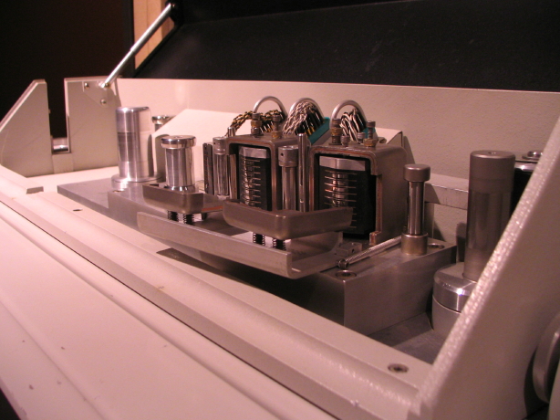
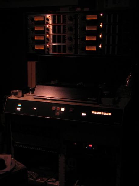
Yeah the avatar thing was kind of spontaneous...I'm not one to change it but that record arming thing was, like, the last hurdle before the transport was finally ready again to be dialed in and when I got it licked and was sitting there jest lookin' at thm purty laghts and in perticuler that one big red one that was it.How exactly do you bump up those voltages to such precise levels? Is it not the transformer in the power supply that sets this initial voltage?
What really has me curious is the peculiar order in which the arming lights come on...