Knightfly, Pucks, and Point Loads

frederic

New member
Steve,

I couldn't find our original thread, wasn't sure if it was on this BBS, or John's, or what thread. Maybe I have too much "mud" dust in my head :(

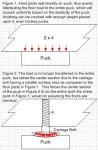
Anyway, I've attached the diagram as promised, and I'm only trying to illustrate a concept here.

This concept is "big" in racing, because point loads generally will cause chassis failure. This is one of the reasons for such fancy triangulation - to spread the load of cornering, weight transfer, acceleration and breaking to as much of the entire chassis as possible at all times. This way, it can remain lightweight since it all the pieces work in unison, rather than any one piece bearing the entire load of the weight/movement/etc.

I had suggested carriage bolts for two reasons - one to make a point load for the reasons stated in the drawing, and second, it is much easier to drill, hammer in a T-Nut, and screw in a carrage bolt than it is to use a hole saw in a drill to bore through the center of a hockey puck. Though, it can be done with liberal use of clamps and such. In fact, one could probably get four rubber columns per puck, if one bores carefully.
 

Attachments

  • pucks.jpg
    pucks.jpg
    48.9 KB · Views: 193
frederic,

You can't equate the engineering required for an automobile that's going to race with that required for building structure. The engineers are after very different things.

I would point out here that another consideration that has to be taken into account is the ability of the framing itself to carry the point load. There will be an increase of forces on that point of the member - with less member to handle those forces.

Once we remove the material where the T-Nut is embedded we have just decreased the cross sectional area of the framing - and have to look at the remaining area of the member to determine if it can now handle the shear and bending that will be imposed on it at the point of the nut.

My guess would be that this is going to force you into (at the very least ) the next larger member size..... and from a cost/benifit point of view - may well make it not a viable construction method.

The analysis is not complete just by determining if it works with the puck (or pad) - but has to follow through all of the assembly.

Think about it,

Rod
 
Last edited:
Oooops :)

I see one problem with this Puck idea. The elasticity of the Puck VS the elasticity of the wood forced vibrational loads back into the wood (weakened by drilling) defeating the purpose of the Puck. By creating a peak load condition on the puck you will actually compress the puck material into something thats probably equal with a concrete slab. Remember how structural loads transfer and the basics of isolation.

If you drilled a hole partially into the puck and filled it with a medium durometer elastomer you could dampen and control positional tolerances so there is no drift :)


Nice pic Frederick...

SoMm
 
I'm going to show my stupidity (not being a structural engineer)... it sounds to me like you all are suggesting that you SHOULD concentrate the load on the pucks... as in the carriage bolt example...

why? I am assuming two things... 1) if the puck is compressed too much, it will negate its ability to decouple the floated floor from the original floor and 2) you'd also be creating a structurally weak point in the 2x4 member where the shaft of the carriage bolt is into the 2x4.

Just curious.

Velvet Elvis
 
Velvet Elvis said:
2) you'd also be creating a structurally weak point in the 2x4 member where the shaft of the carriage bolt is into the 2x4.

Velvet,

Re-read my post - that was one of my concerns - you must have missed it (i am an engineer by the way)

Rod
 
Rod,

Yes... I read yours.. sorry... I should have directed it more at frederic.

The only assumption I can make about WANTING to compress the puck to the point of stable compression is that it would elimate the floor feeling "squishy" and still maximize the decoupling... but I'd still be concerned that I have the weight of my floor resting on the remaining inch of 2x4 because I drilled out the rest of it to sink the bolt into the wood.

Granted the wood would compress against the side of the bolt under even load and most likely not break, but in the case of a direct load at the outer edge of the bolt, straight down, I would think it would be pretty weak at that point.

Ok... I'll stop my rambling :)

Velvet
 
Rod Gervais said:
Velvet,

Re-read my post - that was one of my concerns - you must have missed it (i am an engineer by the way)

Rod

It gets difficult to analyze because most 2X4's have a variable density where you can't always determine how much capability has been lost by the hole for the carriage bolt hole. Its KNOT as easy as it might seems ;)
I assume if washers are being used some of the load will redistribute some, but we need to talk grain direction, porosity, moisture content and size of hole on top of it all.

Who want to build the FEM of the house?

SoMm
 
SoMM...

I agree totally... but the assumption is still regardless of the chunk of lumber, that removing material... and then centering a load on the portion of the wood where material was removed must not be as structurally sound as the 2x4 being supported along the enter 3 or 4 inch surface of the puck.

Ideally I would think that it would make sense to take a puck and cut an X in it using a dado cutter or something of the sort and then placing the pucks at the intersections of the 2x4 and the cross bracing members... that would maximize the load support per puck.

Am I way off?

Velvet Elvis
 
Rod is correct, the goals of an engineer designing a race car is very different from an architectural engineer's goal. I am neither, however I have some experience with the former, so I try to draw on logic that I'm comfortable with.

I guess no matter how I slice it my idea sucks :) Maybe it would have been better to suggest turning the puck down on a lathe to an upside down trapazoidal cylinder, so that the 2x4's aren't drilled and weakened and the point load is passed down to the concrete below.

How about we all skip hockey pucks :) heh-heh. Thanks for the good comments everyone, I learned something here. I'll stick to cars :)
 
Last edited:
Velvet Elvis said:
SoMM...

I agree totally... but the assumption is still regardless of the chunk of lumber, that removing material... and then centering a load on the portion of the wood where material was removed must not be as structurally sound as the 2x4 being supported along the enter 3 or 4 inch surface of the puck.
True, I was just adding that an assumption of perfect lumber is fanatasy so the in reality the situation is much worse than the original assumption. Thats why is important to figure out the properties of the particular grade of material your planning on using.

Velvet Elvis said:
SoMM
Ideally I would think that it would make sense to take a puck and cut an X in it using a dado cutter or something of the sort and then placing the pucks at the intersections of the 2x4 and the cross bracing members... that would maximize the load support per puck.

Am I way off?

Velvet Elvis
That would be a better option, it would also help in "tooling" during frame assembly, you might even use a flexible adhesive and bond them before nailing/screwing the frames.
If you were good you would custom cut the slot depth to each loacation to perfectly level the puck position.

Ive been staring at the feet on my pool table for leveling a drum riser Im designing.


SoMm
 
Hey frederic... I've got the solution!!!

Just build racecars... and then record inside of them :)

I actually did this once... cutting an album at a guys house in a small town...

He had a HUGE garage out back, so we ran a snake from the house to the garage... setup the drums in the garage... then put the guitar amps INSIDE of cars to maximize isolation :)

It actually worked really well.... and how many others can say that the "bass guitar equipment included a fender jazz bass, a hartke head and cabinet, an old turner broadcasting mic and an 87 Ford 4-door" :)

Velvet Elvis
 
SoMM,

I had an idea for a drum riser as I was walking around Menard's (one of our mega home improvement stores)...

They have 2x2ft squares of OSB sub floor already sitting on top of a grid of rubber/pastic discs. This thing was designed to put a subfloor in the basement where moisture is a concern etc.

http://www.dricore.com

I'm just planning on making an 8x8 platform out of these things and then covering it in carpet.

I also thought about putting the whole shooting match on top of these things, but I my studio is going in a concrete basement, and I think I really only need to worry about the drums and bass guitar causing issues.

Velvet Elvis
 
Just build racecars... and then record inside of them :)

The last race car I built (or partially built, never got past the chassis testing phase :( ) had room for one adult, practically lying down, and that was it. On the passenger side was all the electronics for engine management, valvetrain control, air shifting controller, and ABS.

It actually worked really well.... and how many others can say that the "bass guitar equipment included a fender jazz bass, a hartke head and cabinet, an old turner broadcasting mic and an 87 Ford 4-door" :)

heh-heh, if it works it works :)

The strangest place I recorded a drumset was in an open field on two 4x8 pieces of plywood laid down. We did this to avoid any possibilities of echos, and aside from noisy critters towards the evening hours, the session went well.

Amazing what people do when they don't have a studio to record in. heh-heh. I do like your Ford isolation booth idea, clever indeed. If its anything like my Ford truck, you got a lot of interior vibrations and squeeks!!!!!
 
Looks like a pretty economical way to make a drum riser base. Its too bad they don't have a dealer in the PNW. Im in a garage studio and I haven't finished my floors, 1/2 bare concrete and 1/2 carpet, cold and ugly. I can't do the studio floor until I replace the carpet in the family room as part of a deal struck with my wife. Those dricore things would work great for a base for the wood floors. Thanks for the idea and the link.

SoMm
 
http://www.dricore.com

I'm just planning on making an 8x8 platform out of these things and then covering it in carpet.

Dricore is VERY cool, at least from my 4 minute experience fondling it at the Home Depot display. I was originally going to lay the engineered light maple pergo flooring over a thin layer of neoprene sheet on my studio floor, but when I saw the dricore I saw several advantages. First, a little more sound isolation, and second, it supposively "warms" the floor by locking in an air layer. THis might be better for me to keep from having to insulate the garage ceiling at this very moment in time. Cleaning out both bays, then removing both bay's worth of plaster and wire mesh, just is an unpleasant job for the winter. So this might be a good solution for even me.

I like that its a snap-fit too, easy to work with. The HD display didn't have a price tag associated with the material, and the two zombies in orange aprons I asked had no clue, but it did look and feel like a quality product.

Not that I have any clue what i'm talking about. And I'd have to shave my entrance door too :)
 
At Menard's this stuff was somewhere around $4 for a 2x2 sheet...


so for me, looking at a 18x21ft room, I'd need to spend somewhere around $1500... BUT the floor would be isolated, level and subfloored all in one step.

Velvet Elvis
 
Velvet Elvis said:
At Menard's this stuff was somewhere around $4 for a 2x2 sheet...


so for me, looking at a 18x21ft room, I'd need to spend somewhere around $1500... BUT the floor would be isolated, level and subfloored all in one step.

Velvet Elvis


Bingo, mine would be a hair less because my room is 13x20, minus the vocal booth of 8x6, and I get the home depot contractor's discount as well since I'm a non-practicing but registered in NJ contractor :)

I get to save a whopping 8-10% depending on the items.
 
Son of Mixerman said:
It gets difficult to analyze because most 2X4's have a variable density where you can't always determine how much capability has been lost by the hole for the carriage bolt hole. Its KNOT as easy as it might seems ;)
I assume if washers are being used some of the load will redistribute some, but we need to talk grain direction, porosity, moisture content and size of hole on top of it all.

Actually - the assumption above is not exactly accurate.

In fact we do design all the time based strictly on the type of material - taking into account the grade classification - and the fact that wood does not generally have uniform grain patterns is taken into consideration, as is the rest of the points mention above.

Otherwise we would never be able to do anything other than over design any structure.

It is easy (for an extreeme example) to model failure in a 2x6, # 2 construction grade, Doug Fir Larch, floor Joist with a 12' span carrying a 10psf dead load with a 40psf live load.

Each and every material has a very specific modulus of elactisity, fiber bending, sheer, tension and compressive strengths, and thus it is no problem determining the value for a particular material sight unseen.

Is it possible to have one particular piece of material which might have slightly more strength in one area of it's body than is noted on the structural tables? The answer is obviously "yes" - HOWEVER - will the majority of pieces of a particular material have the properties listed within the tables - you can count on it.

It is therefor quite easy to check the remaining cross sectional area of any given material and determine whether it's capable of carrying a particular super-imposed load.

Sincerely,

Rod
 
Rod Gervais said:
Actually - the assumption above is not exactly accurate.

In fact we do design all the time based strictly on the type of material - taking into account the grade classification - and the fact that wood does not generally have uniform grain patterns is taken into consideration, as is the rest of the points mention above.


You missed the humor you knotty boy!

I wasn't making an exact assumtion... Assumptions are rarely exact, thats why everything is overdesigned. Not having a uniform grain means your calculating based on generalities and not specifics, Im taking specifics, building a FEM that has knots, gaps, splits and even the shear of the carriage bolts on the hole. If thats easy to calculate on paper Ill be monkeys uncle. Its not even remotely fun on a computer with semi decent automesh.
My main point, when you get down to the nitty gritty it gets difficult to analyze the various imperfections inherent to any material. When you do your analysis I assume you have a margin of safety or factor of safety that is part of that calculation. Isn't most of the lumber visually inspected and placed in its grade anyhow, with some sort of sampling scheme (test coupons) in place?

Like you said... average properties are taken into consideration.


Designing without allowables is what most of what goes on in DIY forums. It would be rare to see a guy NDI his lumber and map the defects in a 3-d mesh before drilling. Even though I should have done it once when building my studio.

SoMm
 
Back
Top