+4/Bal to -10/Unbal & vice-versa - conversion options...?

There is a lot of reading here which I admit I have not read all of it, but by not using the tape returns you are making the routing of the 3500 less flexible. Why don't you just make up a balanced to unbalanced +4 to -10 pad for each tape input and connect to the tape returns? The pads are very cheap to make, just a few resistors, if you have a patch bay you could even build it into the back of that. This is how I have my M3700 wired and it works just fine. All the info here.

Alan.
My thoughts exactly Alan. The (slight) problem with cutting the send signal to neg 10 is that you loose the noise advantage of working at the higher level. There might also be an increase in source Z, certainly will be if the original outputs were configured as "zero impedance" drives.

Also, anytime you are forced to send unbalanced signals a long way try to use a "shielded return" system. In this the audio hot and return are included in an overall shielded cable but THAT shield is connected to mains earth, not signal. I have a 20ft run from a Teac A3440 of all 4 tracks and the hum on the line is at -93dBFS, rather better than the hum from the heads! That is using CAT6 FTP cable BTW.

Dave.
 
Was this a technical choice, or some other reason? Just curious.


oops, never mind. Just reread your reply. Carry on.
No, fair question SM.
1) It has very tightly twisted pairs.
2) It has a characteristic impedance of ~100Ohms and so can be used with interface boxes to carry VGA, S/PDIF, USB and other signals (MIDI goes well too!)
3) Cheap as chips
And four? I was in the industry for 10 years and had clicks of the stuff!

Dave.
 
In this the audio hot and return are included in an overall shielded cable but THAT shield is connected to mains earth, not signal.
Hmmm, not being an electronics savy person, I'm curious where you connected the outer shield..ie .."mains earth". Do you mean like a chassi ground? Or directly to the AC ground, which may be the same as chassi ground but you tell me?:confused:

btw, I've read tons of articles on studio grounding issues, but always get bogged down in technical stuff. I finally decided if to KISS it.(keep it simple stupid!..ie..just plug it in and hum be damned:D)

btw, when you say.. "the audio hot and return are included in an overall shielded cable"..by "return"..do you mean "ground"? Also, the FTP thing..arn't these twisted pairs covered in their own shield too?(..ie ..the foil? Never tore into a CAT 5/6 cable so I'm not familiar with it.)
 
No, fair question SM.
1) It has very tightly twisted pairs.
2) It has a characteristic impedance of ~100Ohms and so can be used with interface boxes to carry VGA, S/PDIF, USB and other signals (MIDI goes well too!)
3) Cheap as chips
And four? I was in the industry for 10 years and had clicks of the stuff!

Wow, that was fast. Damn I love the net!:D

Ok, cool. Curious though what the "impedance" thing means as far as using it for audio?
I was under the impression the important thing was "capacitance"..at least for common audio cable. But like I said..I'm no electronics tech.

So, you can use it for other stuff too. Interesting. So is your local terms..like "click":DThanks.
 
It's a lot easier to fine-tune grounding and cable wiring schemes when you have the cables going directly/only from one device to another.
With the schematics or just trial-n-error, you can deduce which way to go for minimum hum/ground issues.
The audio ground - chassis ground thing gets "blurry" for a lot of gear, since not all gear manufacturers follow one grounding scheme. You can tailor your connections from gear-to-gear to adjust for that and find the best-case wiring combination.

However, when you have a bunch of gear, all going to a bunch of bays, and connections are constantly changing, and being combined/interconnected, with a mix of unbalance and balanced gear...it's not as simple or straightforward. If you use a specific wiring scheme for one combination, it could change as you interconnect other gear via the bays.
In my own setup, I spent a lot of time reading (Rane Notes was my favorite source)...and I went with basics, following what would be the most used/best case schemes wherever I could.
I star-grounded everything back to earth-ground.

With all the gear I have, and even the longer unbalanced runs...I've only had maybe 2-3 pieces of rack gear give me a little trouble, and for them, I found an alternative way, often just a simple jumper wire from the chassis to some other point...and that removed the hum. Mind you it was always very minor stuff. I never had serious ground/hum issues.
I also ran dedicated power lines direct from the main breaker-box, on their own breakers. I also use a couple of 20 Amp voltage regulators/power conditioners, and all the gear plugs into them...actually, I just use one, the other is a spare, and only there if I need to have EVERY piece of gear on at one time, including all my guitar amps, which would be too much for 20Amps...:D ...but that's never been the case. Even at mixdown, where the most gear is used, I can run on one.
I considered adding a balanced power box a few times...but my AC is actually very good/quiet, so I've held off, as those boxes are not cheap.
 
Chronicle: Heh! Ground loops can confound the best of men! So, shielded return.

Consider a simple feed from an unbalanced computer 3.5mm (ugh!) jack to a fairly remote hi fi amp. The lead would be a single core carrying the "hot" signal and an outer shield which does double duty as the "return" wire (we must ALWAYS have a circuit remember, no matter HOW feeble the current) and is expected to keep electromagnetic crap out as well. The trouble is it don't, well, certainly not well if the lead is a long one.

So we use two core cable and use the "black" wire as the return in the jack plug. The overall shield is never connected directly to THAT audio earth but to computer chassis or, as in my case, the earth pin of a 13amp plug. The remote end of the shield would not normally be connected at all. In my Teac case it does connect to a steel breakout box, but the audio return does not. No currents can be induced in the shield and even if they were they cannot mix with the audio return wire.

Senior Member: You are correct. Capacitance is the only parameter about audio cable that we need to bother about and even that only for special cases ( e.g. guitar leads). I mention the 110R thing because things like S/PDIF are 75Ohms and the boxes I reffered to are "baluns" that take ubal 75R and transform it to balanced 110R and step it back down tother end. Up to 300mtrs is claimed for these!

Clicks!? The UK is resisting SI units mightily but really should be well metricated by now. I am happy with imperial or SI but tend to go metric for the forums as MOST of the countries of the world have seen the light!

Dave.
 
So we use two core cable and use the "black" wire as the return in the jack plug. The overall shield is never connected directly to THAT audio earth but to computer chassis or, as in my case, the earth pin of a 13amp plug. The remote end of the shield would not normally be connected at all. In my Teac case it does connect to a steel breakout box, but the audio return does not. No currents can be induced in the shield and even if they were they cannot mix with the audio return wire.

Hmmm, so if I understand you correctly, you are saying that UNBALANCED cables, such as from my computer/mixer/fx/tape machines etc, SHOULD be a cable with two conductors and a shield..same as balanced or mic lines...but utilizing the Black as a "return"(aka signal ground?), and the shield connected to earth ground at one end only..is that correct? If so, what determines which end of the shield is connected to earth ground? And how would one accomplish this when using RCA, or 1/4" PHONE plugs, as 99% of my gear in's/out's are these types. How do you isolate the shield from the plugs outer casing? And then, what about Patch bays. Seems to get pretty complicated, with all these shields being connected to some other earth ground point. Hell, my cabling system is pretty complex as it is, even as small as my system is. 5 Patch bays, 2 16trk R@R, (2) 2trs, 32 ch mixer, and all the other stuff...sounds like a mind f--k to me. Not to mention changing all my single conductor shielded cables! Yikes..
(visions of soldering that many plugs isn't fun, not to mention the shield thing! umm..the KISS system may have to do!:p )

Consider a simple feed from an unbalanced computer 3.5mm (ugh!)
Ha! Just tackled all the 3.5 mini stereo in's out's from my 2 computer system yesterday. Took all day just to connect it to a custom splitter box. I absolutely abhor adapters , so I made up cables with 3.5mm stereo plugs to XLR to isolate the grounds, which then separate L/R inside the box with Phone jacks out to a regular Patchbay, with the outs going to my SS playback system, which is pretty convoluted too.

On one computer(EVGA mobo) I use the mobo audio outs for a 6 point surround(front/rear/sub stereo outs, 1 stereo line in) when I just want to entertain my self with Internet stuff(music/movies etc), but it also has a Maudio 1010lt for recording, with it's own set of cables/breakout box. I select between the two within Windows. The second computer is for Aux stuff, like Midi/other, using a Soundblaster audio card in/out, to the same breakout box to Patch bay.

So all in all, my computer system alone would qualify for a cabling upgrade mind f--k.:eek::p

btw, speaking of mind f--k, had to layout the cabling system in Sketchup just to see where everything goes...just using a simple KISS technique. Can't even imagine what it would look like with the shield thing...gak! Besides..I haven't even finished the Sketchup, let alone the real wiring!
(note..trying to upload attatchments...prepare for Frustration attack:rolleyes:)

Anyway, thanks for all the info. It DOES help.
 

Attachments

  • Studio Wiring Diagram Over All.jpg
    Studio Wiring Diagram Over All.jpg
    56.5 KB · Views: 15
  • Computers.jpg
    Computers.jpg
    82.6 KB · Views: 16
  • Studio Wiring Diagram.jpg
    Studio Wiring Diagram.jpg
    96.8 KB · Views: 15
  • Maudio 1010lt Breakout Box.jpg
    Maudio 1010lt Breakout Box.jpg
    101.7 KB · Views: 16
:mad::mad::mad: Well..AS USUAL..only two of 4 of the attachments actually ATTATCHED!!:rolleyes::cursing::cursing::cursing::cursing::cursing::cursing::cursing::cursing:


Ya know, you'd think the webmaster here would get tired of people bitchin and DO something about it...

but NOOOOOOOOOOOOOOOOOOOOOOOOO!!!!!!

same ole shit. different day. All I gotta say is ...this place is getting pretty fucked up.:rolleyes:
 
No,no,no,no,nooooo! The technique of shielded return is only used when you are forced to send signals over a decent distance but balancing is economically impractical (8 traffs in my case or a serious amount of electronics) . The system is also very useful if RFI is at a high field strength (saved my A on a magnetic cartridge feed on a theatre pan deck some years ago.). You really need breakout boxes both ends anyway.

Normal balanced operation is best and short unbalanced connections are also usually quiet....In any case! You got time for all that drawing you got time for some slodering!

Dave.
 
No,no,no,no,nooooo! The technique of shielded return is only used when you are forced to send signals over a decent distance but balancing is economically impractical (8 traffs in my case or a serious amount of electronics) .

OOOOOOOOOOOOOOOOOOOOOOOOOOOOOH/!! Gotcha! Ok, cool. That clears it up then.

In any case! You got time for all that drawing you got time for some slodering!
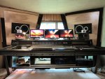
Already did all my soldering. 90% of my cables are DIY. It is the drawing that helped me identify where various sets of cables had to connect at each end in my console. Once the equipment was placed, then I could approximate the required length, so I don't have tons of "too long" cables coiled behind my console. Been there, done that...did I mention I hate cordballs:D In fact, it was my hatred of cordball messes over the years that dictated the drawing this way. I have 4 metal cable tie down tubes running the full length of the console at the rear to keep everything neat. Here is the console. It's still not finished, although I'm getting real close. Just have to finish the second computer mod and purchase a few goodies for it.

And btw, the furthest thing from the console that has to be connected is my twin MSR-16's, which are only 5' from the patchbays, and I have unbalanced 8 cable snakes. And actually, since I never have a need for sending more than the 8 buss outputs, I have another patchbay at the tape machine fixture, to patch to what ever tracks on each machine I need. The tape machines are synched via midiizer, so the tape returns are all connected to the tape in's at the mixer.

The technique of shielded return is only used when you are forced to send signals over a decent distance but balancing is economically impractical

The tape return snakes are only 8' long so I don't think I need to adapt the technique you describe. The tape machine fixture in the Sketchup is already built, and sits to the right of the console within arms reach. Don't have a pic of it in that location though. The sketchup shows it in a machine closet at the rear of the room. That area now is being used for a diffuser.
It's only half built in the shop right now. And that's the problem with DIY. Too many projects..too little time.
 

Attachments

  • studio1.jpg
    studio1.jpg
    71.6 KB · Views: 20
  • is.php?i=364&img=5212Tape_Machine_Fi.jpg
    is.php?i=364&img=5212Tape_Machine_Fi.jpg
    41.1 KB · Views: 22
If my cable runs looked half as good as those drawings.....


Well, actually, that was the whole point of drawing them..so the rear of my console DOES look that organized. Alas, I'm not there yet though.

Thanks miroslav, Sketchup is a tool for me to visualize everything in my studio. It's called design. I couldn't have built a lot of the things in my studio without it, like the soffits the computer enclosure and various diffuser/absorption fixtures. Here's the enclosure.
 

Attachments

  • is.php?i=1393&img=7_Computer_Encl.jpg
    is.php?i=1393&img=7_Computer_Encl.jpg
    43.1 KB · Views: 21
  • vert section computer enclosure.jpg
    vert section computer enclosure.jpg
    50.1 KB · Views: 20
Well, actually, that was the whole point of drawing them..so the rear of my console DOES look that organized.

My cabling is organized, neat and tidy, and everything labled....but in your sketches, it's all perfect! :D
Each run is straight as an arrow and square and everything has it's individual pathway with nothing touching...
...that's what I meant. Not sure if I could get them that perfect in real applications.

You know...your sketches are very familiar. I've seen them before on this forum, but posted by someone else....?
 
You know...your sketches are very familiar. I've seen them before on this forum, but posted by someone else....?

oh come on miroslav...you know who I am. The asshole from Oregon..remember. btw, I take my meds regularly now so don't be nervous. Their called HRD....


...Vodka. :D

ps. sorry for being an old Irish prick. I'm better now. Even my wife thinks so.:laughings:
 
Your secret is safe with me.... ;)
I didn't want to out anyone openly on the forums....but I knew.

We'll let it be like this.
Your other persona is just forum history...... :)

So...you ever gonna' finish that thing?
You know, it's not the ceiling of the Sistine Chaple! :D
 
So...you ever gonna' finish that thing?

If it doesn't kill me first.:facepalm::D But I'm makin headway. My biggest problem the last three years was taking care of my wifes Father who had Alzhiemers. Fuck. He was just coming down with it when he moved in with us. Never knew what that wretched desease really was about untill then. It was a 24/7 job. He died last October. Been catching up on tons of household stuff. And now...it's my turn..come hell or high water, I'm going to finish up this summer. That is if I don't come down with Alzhiemers myself. Ha. Real trouble is though..I wonder if I remember how to play music.:eek:...Hahahahahahaha!


btw, I just bought the JL Cooper automation package from BRDTS. Can't wait. But now, I'll have to also buy a vintage Mac computer and gut it to put in the modded case for the other side of my enclosure. Maybe. We'll see. No matter, I just wanna see this thing work.


Your other persona is just forum history......
Good. Let's leave him there.:drunk: Thanks miroslave.
 
Back
Top