wall plates quick question

  • Thread starter Thread starter notbradsohner
  • Start date Start date
N

notbradsohner

Compression Addict
what does the back of an xlr wall plate look like. I am looking into building some xlr wall plates into my iso room but i dont know where to start. do i have to wire it myself, or will the wall mounts be like a super short cord, (without the cord.) (two connectors wired together in one housing)
 
Like this. There are three lugs on the back of the connector where the connections are soldered. The connectpr itself would be mounted into a wall plate.
 
The one's that I bought were from soundcraft. They had solder cups in the back of the xlr. Here's what they look like hooked up.
 

Attachments

  • picture 10.webp
    picture 10.webp
    14.5 KB · Views: 220
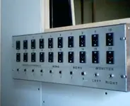
Nice wall plates case!!!! :)
I'm building some as we speak. I'm making mine out of wood (Red Oak).
I was going to start a new thread, but I'll just ask you here, since you're already done with yours.

I'm planning on having a wall plate on each side of the wall (from control room to iso) Then, in the CR, cables from the wall plate to the console, which will run in a cable trough under the floor.
I need phone jacks in my wall plates for headphones.
All the phone jacks I've seen are a straight "hole" through the wall plate. (At least with the xlr's there's a backing to them.)

So, if I have a phone jack on each side, then I have a big ol' 1/4" hole thru the wall. :(

Is there some other jack I should look into, or should I just have the phone jacks.... home run from iso to console and skip the CR side of the wall plate for the phone jacks??? :confused:
 
Mount standard wall boxes offset by at least one, preferably two, stud cavities, run your wires between them (poked thru the insulation, feed the wire into the box on each end leaving at least 8" of wire , then caulk the crap out of the boxes where the wires come though (and everywhere else), finally strip and solder your connections and install the plates.

If you use "old work" boxes, you can avoid having the box touch the studs (mount away from the stud, that's why the "old work" boxes) - this can cut down on flanking thru the box and into framing members. Putting the box in the center of a wallboard panel allows your insulation to help absorb whatever makes it through the box, before it gets to a frame member... Steve
 
Didn't I see someone around here use a surface mount? I remember seeing someone use a similar xlr plate mounted to a wedge shaped box close to or maybe even sitting on the ground.
 
Don't remember seeing that - no reason it wouldn't work, just not as "elegant" - main thing is a long, tortuous, SEALED path from one side of the wall to the other... Steve
 
Sorry, I didn't understand your question Michael. Try again and I'll get back to you on that!

Late,
Casenpoint
 
Here's what the panel looks like from the back. Using my machinist tools I laid out the marks for the hole positions- all of them including xlr screw holes. Punched the marks. I then cut out the xlr holes with a 13/16 pilot/hole saw. I then mounted all connectors to the the face. I then soldered all wires(purchased at clark and wire) that I pre cut at an 8 foot length (making sure it would snake between the walls and come out on the other end with trim left over) to the connectors with some help. It is pretty tough to hold the wires and solder at the same time. I put shrink tubing on all of the sheild(bare wire) so that it will not short on any of the other surrounding wires. I used plenty of solder. Not enough solder can result in having weak signals. With one side soldered and mounted on the box I snaked the wire through the wall and soldered the other end on. I went to staples and bought some transfer letters "designators" 1,2,3,4,5...etc i have 20 xlr 4 trs 4 mono 2 -1/4" speaker(soldered speaker wire). Having 4 headphone jacks means I can turn up the sound on 4 independent channels with the rolls headphone amp. Without the musician having to get up and turn it up himself or herself. Well that pretty much it . i am not an expert by no means I just had to make do by any means necessary.

Later ,
Casenpoint
 

Attachments

  • picture 9.webp
    picture 9.webp
    24.8 KB · Views: 166
Case:
Well, the xlr's have a back to them. So, at least there's some blockage of the hole in the wall plate. But the 1/4" phones don't have a back to them... at least not the ones I've seen, so its a open hole through the wall plate.
How do you avoid that open hole on the 1/4" phone?
 
Oh. I'm looking at your picture again. I think I see now.
All of your cables are routed through a small penetration on the back of the wall plate. Which I imagine is all sealed up nice and snug. ;)

I thought the idea would be NOT to do that (route all cables through a single, small hole) that way, if a cable went bad, you could just un-screw the xlr, unsolder one end, and use the old cable to pull a new one through.

Makes sense now.
 
Michael, it's next to impossible (especially if plates are offset from one side of the wall to the other, as they should be) to pull a new cable in with an old one, unless it's all in conduit - and using conduit negates the sound isolation by a LOT - normally, cables inside walls don't go bad in the owner's lifetime - only occasionally at solder joints (if done poorly) or if they're flexed a lot.

For sound walls, you're probably better off just adding a couple of spares (labeled on both ends) before sealing the boxes, and leaving the pigtail coiled up inside the box at each end for future replacement or expansion... Steve
 
Back
Top