To someone who got a TnC ACM-3. Can you help?

tarnationsauce2

Welcome to the jungle.
Can you do me a favor, grab a flashlight and hold it up to the bottom vents of the mic. Look in there and you'll see a little PC board about 1/2"x1/4"that says something like "R2 2".
Can you tell me if it's on the back or front of the mic?

I took my mic apart, and in my excitement I forgot to note which way was the front of the motor assembly.
 
Hey,, while you have it apart, can you take and post a digi pic of both sides ?
I need to send a pic to "Edcor" (transformers)
 
Hey,, while you have it apart, can you take and post a digi pic of both sides ?
I need to send a pic to "Edcor" (transformers)
I did take some pictures. I hear good things about Edcor, price/performance is stellar.

I do have a bit of mixed feelings that I show these pictures. All of these ribbon mics had excessively loose ribbons except the ACM-4 (dual ribbon). I did go through and tension them all. It's not difficult if you have VERY steady hands, proper tools, a good deal of patience, and awareness of what you are dealing with.

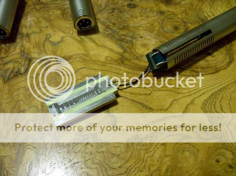
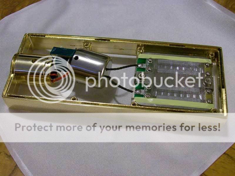
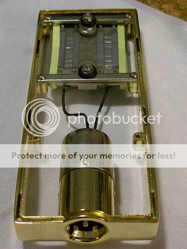
The ACM3 mic body has an i.d. of 23mm. The XLR slug that screws into the bottom is o.d. 22.81mm, and it was able to move all the way through the body.
The amount of free space between the ribbon motor and XLR connector is ~53mm, leaving ~20mm for wiring.

A little YouTube video showing the slop in an ACM-2 ribbon:
(it's a caterpillar!)
https://www.youtube.com/watch?v=nsLDBIOijc8

I followed Michael Joly's tips in this article: http://www.hometracked.com/2007/08/28/ribbon-mic-sag-and-repair/
I should note that he gives a quick and dirty test to see if you have a loose ribbon, to rotate the mic and listen for "clanging around". With these particular mics there is nothing holding the transformers still in th body, and the transformers will clang in there. So you may be hearing that and not the ribbon itself moving.

ACM3_3.jpg

ACM3_1.jpg

ACM3_2.jpg

ACM3_5.jpg


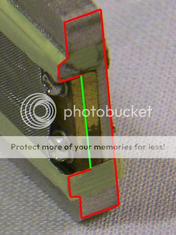
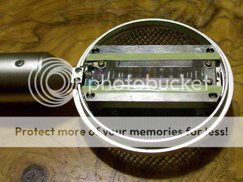
Here is the same pic, but I outlined the profile of the motor, and the line in green is to help show any offset there may be. It's where the ribbon lies in the clamp.
ACM3_4.jpg


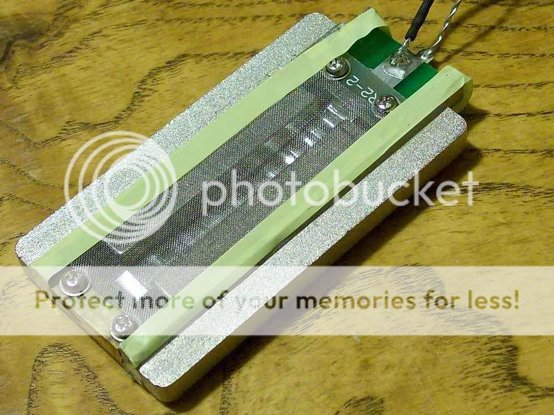
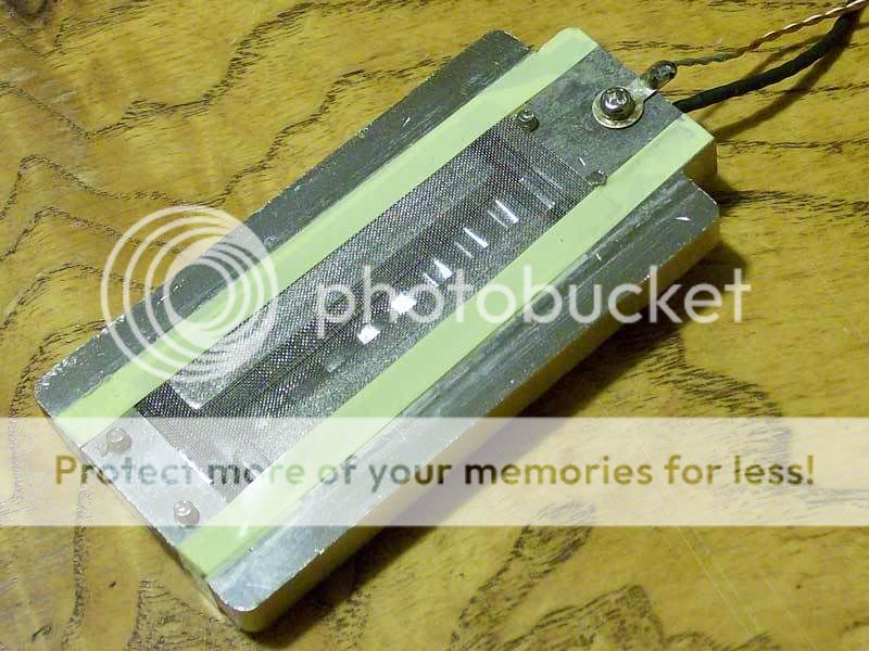
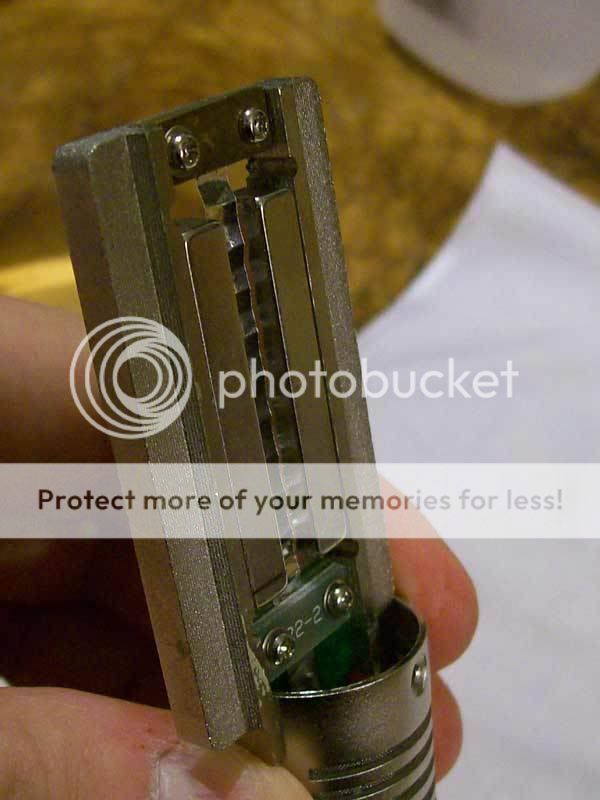
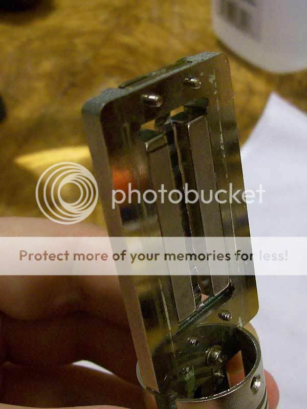
These next two pictures are after I tensioned the ribbon. I tuned it to 35hz. Unfortunately I forgot to take a pic of what it looks like held horizontally after tensioning.
ACM3_6.jpg

ACM3_7.jpg


Here are some pics of the ACM-2 ribbons I got. I also tensioned these ribbons. I tuned the ribbons to 30hz for each. (these pics are not tensioned)
ACM2_2.jpg

ACM2_1.jpg

ACM2_3.jpg


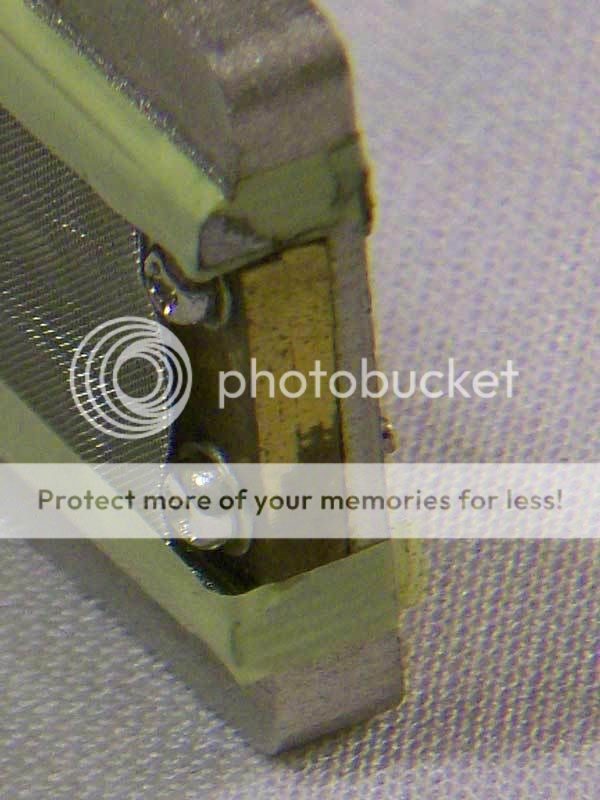
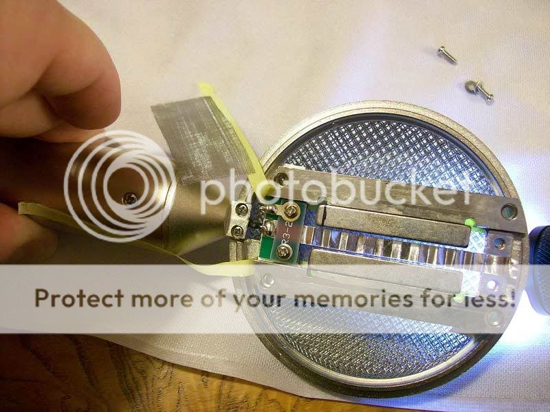
Here is a good way to tell if you have the ribbon equidistant between the magnets. Hold a flashlight under it.
ACM2_4.jpg


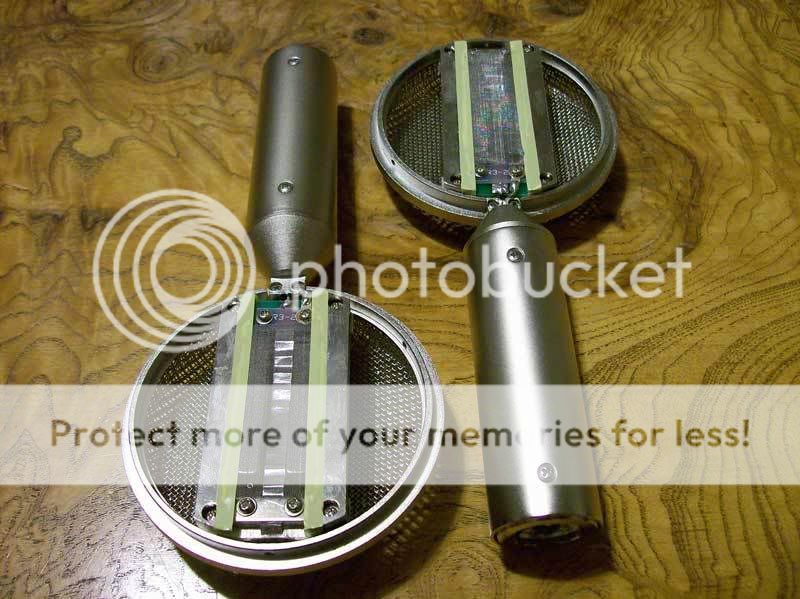
The ACM-4. It is not easy to take apart, I used a plastic hook and pulled up on the grille on one side. Be careful not to dent the grill. there are no screws or glue holding it together. It's just a very tight fitted piece.
ACM4_1.jpg

The ACM-4 is the only ribbon of the ACM 2/3/4 that uses a Mu-metal can over the transformer.
ACM4_2.jpg

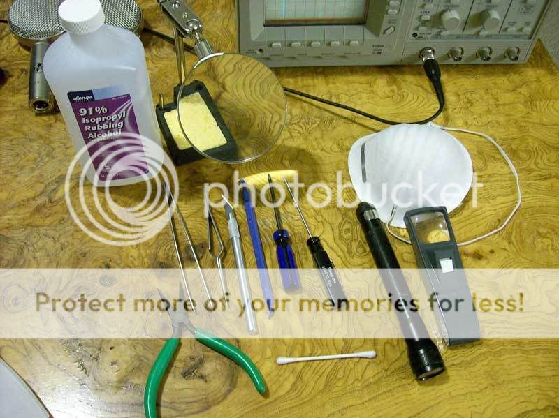
Tools of the trade: Note the dust mask! I am not kidding, a little breath will blow the ribbon like it's nothing. Also make sure you're without a dog, forced-air heating, fan / etc in the room.
ribbon_tools.jpg
 
Last edited:
Ribbon Offset

Nice pics, thanks for that.

Re: Ribbon offset - I was confused by your 5th picture down. But your 7th picture down from the top appears to show the ribbon itself offset toward the back of the magnets.

It is the relative placement of the ribbon in the magnetic gap (centered or offset) that provides either a symmetrical or asymetrical HF response and SPL handling like the Royer R121. The ACM-3 appears to have an offset ribbon placement like the Nady RSM-3 and RSM-5.

In the 7th picture I was trying to illustrate the shape of the motor, and where the ribbon is clamped.

Yes, the 7th picture does look like the ribbon is further back (ever so slightly).

As soon as someone answers my initial question to this thread we will know which way it is supposed to go.

My suspicion is that we are looking at the back of the ribbon in the 7th picture. That is how I put it back together.
 
Ribbon offset

I don't have one of the offset ribbon mics open at the moment...

...but I recall the ribbon was offset from center such that one face of the ribbon was only about 1.5mm inside from the surface plane of the magnets, while the opposite face of the ribbon was a good 3.5mm inside from the surface plane of the magnet - quite noticable offset of the ribbon in the magnetic gap in other words.
 
Thank you for the excellent detailed pics. I was asking for pics to send to Edcor, but with your permission, I would like to send them to China. I was expecting some QC issues. I will post what I hear back from them
 
Thank you for the excellent detailed pics. I was asking for pics to send to Edcor, but with your permission, I would like to send them to China. I was expecting some QC issues. I will post what I hear back from them
Sure, no problem. Show them this video too: https://www.youtube.com/watch?v=nsLDBIOijc8

I should say that I have read about cases of ribbons arriving to customers sagging from reputable ribbon technicians. Meaning, that the stretching happened in transport.

I say that because an under-stretched ribbon is better than an over-stretched one. If it is overstretched from the China mfr overcompensating the corrugations could be flattened and that is much more difficult to repair.

The best thing China could do is make the ribbon saddles adjustable with a locking nut. That way it will be a bit less of brain surgery and won't require very steady hands or releasing the ribbon from the saddle. When you do that the potential for damage it quite high.
 
The best thing China could do is make the ribbon saddles adjustable with a locking nut. That way it will be a bit less of brain surgery and won't require very steady hands or releasing the ribbon from the saddle. When you do that the potential for damage it quite high.


Spot on. The original Tape Op group buy had tension adjustment separate from the ribbon clamps. This design feature was eliminated during subsequent evolutions of the original 2" ribbon mic as a way to further reduce cost. But that tension adjustment method wasn't ideal. An improved independent ribbon tension adjustment should be obvious to "one skilled in the art" as they say in patent parlance.
 
Well, fart. Mine's way sagging, so bad that it looks like some of the corrugations have gone out of it, but it seems to work.
 
I just got off the phone with China. I demanded an explanation of these slack ribbons. They wanted to see those jpgs and the video. I just E-mailed this info to them. I'll report tomorrow what their reply is.
 
I just got off the phone with China. I demanded an explanation of these slack ribbons. They wanted to see those jpgs and the video. I just E-mailed this info to them. I'll report tomorrow what their reply is.

I don't have a camera. Mine's so bad it looks like it touches the inside screen. It's given me a bad feeling about ribbons, especially after watching that video. I'm too klutzy for something this delicate.
 
In the 7th picture I was trying to illustrate the shape of the motor, and where the ribbon is clamped.

Yes, the 7th picture does look like the ribbon is further back (ever so slightly).

As soon as someone answers my initial question to this thread we will know which way it is supposed to go.

My suspicion is that we are looking at the back of the ribbon in the 7th picture. That is how I put it back together.

The side with the screw heads of the ribbon clamps goes toward the front.
 
I don't have one of the offset ribbon mics open at the moment...

...but I recall the ribbon was offset from center such that one face of the ribbon was only about 1.5mm inside from the surface plane of the magnets, while the opposite face of the ribbon was a good 3.5mm inside from the surface plane of the magnet - quite noticable offset of the ribbon in the magnetic gap in other words.
So I guess it's safe to say that the ACM-3 is not an offset ribbon.
I think that would be easily modifiable with 4 or 8 washers and slightly longer screws. ;)


Also, a very cost effective way to make an adjustable ribbon saddle would be to make it screwed in loosely, with about 1/8" of movement. Then simply tighten it down where the ribbon is properly centered and tensioned. This isn't as good as a lead-screw system for fine tuning of resonance. But mfg costs would be about the same as they already are and there'd be at least some level of adjustability.

And Thank You APL!
 
Also, a very cost effective way to make an adjustable ribbon saddle would be to make it screwed in loosely, with about 1/8" of movement. Then simply tighten it down where the ribbon is properly centered and tensioned.

This is how the Tape Op group buy ribbon motor was done - the clamps held the ribbon securely, but were allowed to temporarily slide forward & backward by the use of screws sliding in slots. The screws then would be tightend down. I sent Chance pics of this design when this GB was getting organized. This is a minor improvement over the present system, but you're right, a lead-screw driven platform is absolutely the best way to go and would allow single-Hz accuracy of resonant frequency tuning.
 
It's given me a bad feeling about ribbons, especially after watching that video. I'm too klutzy for something this delicate.

I hear ya. I guess I'll have to open mine up to see though. And how much do those "tools of the trade" cost?
 
Back
Top