You are using an out of date browser. It may not display this or other websites correctly.
You should upgrade or use an alternative browser.
You should upgrade or use an alternative browser.
sweetbeats
Reel deep thoughts...
Grounding the supply doesn’t do anything to protect the supply. It does two things: first and foremost it provides a path for current in the event there is a failure in the neutral conductor. It ensures current goes to ground through the “safety” ground instead of through you. That’s the primary purpose of the third prong on a three-prong power cord; safety. The other thing we can use it for is a common ground reference for all the devices in a system, but there are layers to that in terms of how each device handles bonding of the shield connections of your inputs and outputs to the chassis (if at all), and how 0V references of any regulated power supplies bond to the chassis (if at all)…basically discovering how each device handles signal, shield and power supply grounds and getting them in alignment with each other to minimize the impedance of each shield’s path to ground and mitigate ground loops in each device and throughout the system as a whole, and then ensure each device in the system has the same ground reference to the building power. But, again, note none of that has anything to do with protecting the device. That’s done through spike and surge protection, which varies by device, or an isolation transformer, and/or battery backup system. Your M-520 wouldn’t likely be harmed by a brownout. It just might not function correctly during a brownout. I was more interested in if you’d had any electrical storm activity, power outages, etc. It’s always best practice to disconnect devices from power during electrical storm activity, or if power goes out disconnect from power until power is back online. Or have devices connected to adequate spike/surge protection.
I remember not liking how Teac handled the bonding of the 0V references for each supply rail to the power supply chassis, and I modified mine…I can’t recall the details now but it was something like the provision was there for things to be correct, but not everything was correct. I might be able to look back in pictures from 15 years or so ago and refresh my memory…
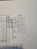
What make/model is your multimeter? Tell me about that first. But after that, look on page 4-6 of the service manual. That’s the power supply schematic. On the right hand side is a diagram of the power supply connector. So you disconnect the supply cable, and probe the appropriate pins to measure the DC output as well as measure for AC. You’ll see most of the rails use two pins each on the connector:
Measure across:
*Pins 1/2 (positive probe) & 8/9 (COM probe), this should measure close to +15VDC, and 0VAC (this is the positive audio power rail)
*Pins 14/15 (positive probe) & 8/9 (COM probe), this should measure close to -15VDC, and 0VAC (this is the negative audio power rail)
*Pins 6/7 (positive probe) & 12/13 (COM probe), this should measure close to +18VDC, and 0VAC (this is the positive audio power rail for the balance amp)
*Pins 19/20 (positive probe) & 12/13 (COM probe), this should measure close to -18VDC, and 0VAC (this is the negative audio power rail for the balance amp)
*Pins 3/4 (positive probe) & 10/11 (COM probe), this should measure close to +5VDC, and 0VAC (this is the LED lamp power and maybe logic? Can’t recall for sure…have to refresh my memory as to the M-500 guys)
*Pins 16 (positive probe) & 10/11 (COM probe), this should measure close to +48VDC, and 0VAC (this is the phantom power rail)
*Pin 17 & 18, this should measure close to 11VAC, and 0VDC (this is the AC rail and it powers the VU meter lamps…it doesn’t matter which probe goes on which pin)
I remember not liking how Teac handled the bonding of the 0V references for each supply rail to the power supply chassis, and I modified mine…I can’t recall the details now but it was something like the provision was there for things to be correct, but not everything was correct. I might be able to look back in pictures from 15 years or so ago and refresh my memory…
What make/model is your multimeter? Tell me about that first. But after that, look on page 4-6 of the service manual. That’s the power supply schematic. On the right hand side is a diagram of the power supply connector. So you disconnect the supply cable, and probe the appropriate pins to measure the DC output as well as measure for AC. You’ll see most of the rails use two pins each on the connector:
Measure across:
*Pins 1/2 (positive probe) & 8/9 (COM probe), this should measure close to +15VDC, and 0VAC (this is the positive audio power rail)
*Pins 14/15 (positive probe) & 8/9 (COM probe), this should measure close to -15VDC, and 0VAC (this is the negative audio power rail)
*Pins 6/7 (positive probe) & 12/13 (COM probe), this should measure close to +18VDC, and 0VAC (this is the positive audio power rail for the balance amp)
*Pins 19/20 (positive probe) & 12/13 (COM probe), this should measure close to -18VDC, and 0VAC (this is the negative audio power rail for the balance amp)
*Pins 3/4 (positive probe) & 10/11 (COM probe), this should measure close to +5VDC, and 0VAC (this is the LED lamp power and maybe logic? Can’t recall for sure…have to refresh my memory as to the M-500 guys)
*Pins 16 (positive probe) & 10/11 (COM probe), this should measure close to +48VDC, and 0VAC (this is the phantom power rail)
*Pin 17 & 18, this should measure close to 11VAC, and 0VDC (this is the AC rail and it powers the VU meter lamps…it doesn’t matter which probe goes on which pin)
Last edited:
flyingace
Active member
Okay! I measured all according to above and all is to perfect voltage except the +15 and -15 DC voltages! (Pins 1/2 - 8/9 0 DC, 0 AC; Pins 14/15 - 8/9 0 DC, 0 AC)
Last edited:
sweetbeats
Reel deep thoughts...
That’s what I suspected.
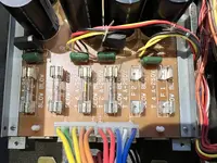
You can’t tell if fuses are good by looking at them. Pull them out and set your meter to resistance and make sure you have continuity across each fuse.
You can’t tell if fuses are good by looking at them. Pull them out and set your meter to resistance and make sure you have continuity across each fuse.
flyingace
Active member
Thanks. I’ll check them now and report back.
flyingace
Active member
sweetbeats
Reel deep thoughts...
So what I would do at this point is replace the fuses, making sure you replace them with the proper rated parts, power the supply with the console disconnected, re-check the outputs of the +15V and -15V supplies with your multimeter as you did before, both for DC and AC voltage, verify they are correct, and then power down, connect the console to the supply, power it up and see if things are working correctly. If the outputs are wonky, or the fuses blow either when you power supply is isolated -OR- after you power the console, report back with these details.
flyingace
Active member
Will do! I have the fuses on order and should arrive tomorrow or tuesday. I’ll recheck it and report. Thanks for your help!
R
RFR
Well-known member
I’ve heard many times that it’s better to just leave the gear on 24/7.
Is it possible that any voltage spikes occurred when powering it up and the fuses just gave out?
Any truth to this?
Is it possible that any voltage spikes occurred when powering it up and the fuses just gave out?
Any truth to this?
sweetbeats
Reel deep thoughts...
FYI for future you can probably find these at your local auto parts store.Will do! I have the fuses on order and should arrive tomorrow or tuesday. I’ll recheck it and report. Thanks for your help!
sweetbeats
Reel deep thoughts...
I suppose it’s possible for the filament to age over time…maybe…and become fragile and fall out of spec. I don’t know any of that for certain…pure conjecture. But the important thing to remember here is fuses protect what’s downstream. When there is a fault downstream that causes the system to draw too much current the fuse fails in order to protect continued operation in a faulty state and the potential to damage system components. Fuses don’t generally or necessarily fail if there’s too much power upstream like with a spike. But I don’t know the particulars here, I’m just reinforcing the point of how fuses operate…what they do, and what causes them to fail by design.I’ve heard many times that it’s better to just leave the gear on 24/7.
Is it possible that any voltage spikes occurred when powering it up and the fuses just gave out?
Any truth to this?
sweetbeats
Reel deep thoughts...
And yeah I hear opinions all over the place about leaving equipment on. And I’m not sure there is a clear winner there as far as what to do. What I know is heat kills, so if there is a device that doesn’t have good cooling, leaving it on all the time could shorten service life…but another thing that kills mechanically is the expansion and contraction from heating and cooling between powered and unpowered…this is not as much an issue with point-to-point wired devices or PCB-based devices with good quality glass fiber PCB base material. The other thing to consider is stuff that’s fan-cooled…leave that on all the time and you’ll want a maintenance plan for cleaning the dust out of it. So I think there are a lot of things to consider situationally. Also remember if you have devices with PROMs in them they may need to be powered periodically or there can be component failures there.I’ve heard many times that it’s better to just leave the gear on 24/7.
Is it possible that any voltage spikes occurred when powering it up and the fuses just gave out?
Any truth to this?
flyingace
Active member
Okay, new fuses are in, and rechecked voltages.
*Pins 1/2 (positive probe) & 8/9 (COM probe), this should measure close to +15VDC, and 0VAC (this is the positive audio power rail)
+15VDC VAC meter jumps around from 29, then 5ish, then 0 and cycles that way.
*Pins 14/15 (positive probe) & 8/9 (COM probe), this should measure close to -15VDC, and 0VAC (this is the negative audio power rail)
-15VDC .0010VAC stable
*Pins 6/7 (positive probe) & 12/13 (COM probe), this should measure close to +18VDC, and 0VAC (this is the positive audio power rail for the balance amp)
+18VDC VAC meter jumps around from 31, then 4ish, then 0 and cycles that way.
*Pins 19/20 (positive probe) & 12/13 (COM probe), this should measure close to -18VDC, and 0VAC (this is the negative audio power rail for the balance amp)
-18VDC .0010VAC stable
*Pins 3/4 (positive probe) & 10/11 (COM probe), this should measure close to +5VDC, and 0VAC (this is the LED lamp power and maybe logic? Can’t recall for sure…have to refresh my memory as to the M-500 guys)
+6.41VDC .0010VAC stable
*Pins 16 (positive probe) & 10/11 (COM probe), this should measure close to +48VDC, and 0VAC (this is the phantom power rail)
+48VDC 1.350VAC stable
*Pin 17 & 18, this should measure close to 11VAC, and 0VDC (this is the AC rail and it powers the VU meter lamps…it doesn’t matter which probe goes on which pin)
+0VDC 11VAC stable
sweetbeats
Reel deep thoughts...
What make/model of meter?
Is there any way you can post a link to a video of the meter behavior when probing the +15V and +18V rails?
+18V was stable when measuring for AC voltage when fuses F1 & F2 were dead right?
Do you know anybody with a scope that knows how to use it?
Is there any way you can post a link to a video of the meter behavior when probing the +15V and +18V rails?
+18V was stable when measuring for AC voltage when fuses F1 & F2 were dead right?
Do you know anybody with a scope that knows how to use it?
flyingace
Active member
It's a craftsman from sears like 30 yrs ago and probably more for car electronics. I can make a video.
Yes, the AC was 0 on both +/- 15vdc adn +/- 18vdc when the fuses were dead.
I have a tech 2 hours away with a scope, he mentioned that to me earlier when I reported to him my findings. He said it might have something to do with "issue in the regulation from the transformer" and a scope would be a better measurement tool.
flyingace
Active member
plugged into pin 1 and 8, VAC on meter
sweetbeats
Reel deep thoughts...
So, my friend, if it was me and I saw that on my meter, I’d immediately power up my oscilloscope and take a look. I can’t really put together a hypothesis regarding what’s going on there, and your meter, though it’s a perfectly fine meter for what you are doing with it…would still like to know the model number…it’s probably on the back of the meter inside the rubber case…but if something is oscillating, what you see in the meter may not reflect what’s happening. And the fact the +18V rail was fine when the +/-15V rails were unpowered, and the mere fact the fuses blew…the supply needs some deeper diagnostics. You could always unplug the main transformer from the power supply PCB and check to make sure none of the secondary windings have continuity with the primary…and measure resistance across each pair of secondary wires to see if anything looks weird there…and if that seems okay then power the supply with the transformer still disconnected from the PCB and start measuring AC voltages of the secondary windings and make sure they are correct. But regardless of what you do next, you have to get the supply working right before you connect the console and see if there’s damage there. It may be time to get your tech involved.
sweetbeats
Reel deep thoughts...
Let me see if I can get to my PS-520…it’s currently hooked up to my prototype Tascam console in a rack…and I’m not sure I can get clear enough access to pull the lid and do measurements on the main transformer, but if I can I can put a video up on YouTube so you can test yours and at least rule that out. My hunch is you have one or more bad transistors, and/or may need to replace one or more main filter caps, but I can’t put together how that would create an overcurrent condition and blow the fuses. But we could at least narrow down what’s NOT the problem.
sweetbeats
Reel deep thoughts...
flyingace
Active member
Thanks @sweetbeats! I have sent your comments and video to my friend who knows much more than I do and has the gear/knowledge to do what your talking about. I’ll report back when I get some answers.
Similar threads
- Replies
- 175
- Views
- 57K
- Replies
- 120
- Views
- 22K
I
- Replies
- 27
- Views
- 7K
- Replies
- 13
- Views
- 8K