sweetbeats
Reel deep thoughts...
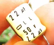
So I'm recapping a set of 4 channel cards...
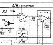
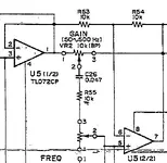
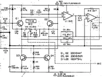
Because I'm having signal reliability and integrity issues on a current project on which the M-520 is being utilized, I figgered it was high time to recap and cleanup (clean and exercise pots and switches) a set of 4 cards and swap out a 4-channel module. I also figured it'd be a good time to test some different opamps. Because there were some question marks about U2, U3 and U7 above I'm just going to focus on U1 (mic preamp), and U5 & U6 (EQ section). My plan is to buy an assortment of 3 ~ 4 kinds of opamps, and outfit 2 of the cards with DIP sockets for U1, 5 & 6...and then try them out.
Questions:
- For bypass caps, would these work well? And if so...
- Are they polar?
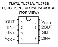
- If I'm using sockets, do I just jumper the appropriate pins of the socket assuming that the opamps that go in there will have the same circuit configuration?
- And here's where the rubber meets the road...do I put the bypass cap between pins 4 and 8??[/
")
")


.JPG)
.JPG)