TASCAM 688 MIdiStudio problem with metering and switching on track 3

altruistica

Member
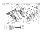
I recently picked up a Tascam 688. It was advertised as parts only. I had one in the past and wanted to try one again. Anyhow, after fitting a new belt to the unit courtesy of a great video on Youtube, I've discovered there is a problem with the metering /switching on Track 3. The unit records and playbacks, but it has a problem switching the signal. I read an old post by 'wkrbee' who said:

'Just a FYI.The 4066 ICs are running at their Max.recommended voltage.The better replacement is the 4966 which has a higher Max recommended voltage.The meters peaking and dropping back on power up is a clear sign you have DC on the audio path-which is typically the failure mode of the 4066-the control voltage shorts to the I/O.'

Now I don't know if that problem is the same one I've got, but I made a short video here to demonstrate it.


Any help offered, gratefully received. Thanks, Al
 
Hey, Al, check your PMs. No clouds-parting magic solution for you, but hopefully something helpful.
 
Interesting…okay.
I didn’t realize the 4966 was in that relative state of obsolescence. And I don’t doubt wkrbee’s suggestion about the driver behind the 4066 failure, but what I do know is the current TI part found here:

https://www.mouser.com/ProductDetail/Texas-Instruments/CD4066BE?qs=mTHRaKC2c7ObpofRtjqLig==

…is rated for +/-20V power. That should be WELL sufficient for the 688’s +/-12V power. Maybe the original 4066 parts procured for the 688 were a lower rated part. Since the original Sanyo LC4966 parts seem hard to come by, and the TI part is readily available, reputable, low-cost and suitably rated, if it was me I’d buy some of the TI parts and put them in. This may address wkrbee’s point of concern.

There are the 4 on the R/P amplifier boards…not sure, as you stated in your video, if these are your problem or not, but there are also 2 on the MONITOR B PCB. There is also one on the PITCH CONTROL PCB. Thinking that is not a contributor. But the 6 total on the boards listed above? If it was me I’d probably just shotgun all 6 with the new TI parts…and have another on-hand in case something gets weird with the pitch control function. Disclaimer: I did not look at the schematics to try and correlate the potential relationship of the 4066 parts to your symptoms, but my semi educated gut-hunch combined with complete trust in @wkrbee and the points he made, as well as my confidence the TI parts are good replacements leads me to suggest it is likely worthwhile to replace them.
 
Thanks Sweetbeats for looking. The part you listed says +/-18v max supply, whch as you say should be enough for the +/-12v of the 688, but lower down it mentions a minimum and maximum dual voltage supply of +/-7.5V. Do you think that may factor in to the choice of 4966 chips? I didn't realise there were 2 chips on theMONITOR B PCB. I wonder if that's where the problem lies, as TR3 monitor doesn't work when the spurious signals stop jumping about......but it still is able to be routed through to either the channel or dual, but without the meter registering what's on tape.
You're lucky being in the States as access to parts seems easier than the UK. Mouser UK has the part you listed though, so I might just buy a bunch and see if that's the problem.
Cheers for the help. Much appreciated.
Al
 
Don’t trust the summary specs Mouser lists…always reference the data sheet…there’s a link there on the webpage for the item I previously linked. The data sheet reflects supply voltage of 20V.

The +/-7.5 is not supply voltage, but signal. So an absolute maximum of +/-7.5 is well adequate.
 
Ah! I see. Thanks for the quick answer. Any tips on removing the buss bar from the mixer panel? It goes right across the board and I'm afraid I might snap a contact by trying to pry it off? I remember the Tascam M3500 had similar buss bars but I think they only connected 4 inputs channels and the 8 groups. I think I need to remove the buss bar to get at the monitor PCBs. Also would you remove the whole mixer panel from the unit rather than attempting the buss bar removal from the raised lid? Cheers Al
 
Looking at it further, it looks like you have to remove the screws from the XLR inputs, the clips that retain the jacks, the other screws at the back of the input panel, remove all pots and fader caps, then the screws at the front of each channel board which hold the frame on which each channel board probably attaches. Also all the screws holding the fader boards, then if I'm lucky, the whole whole of the mixer innards will detach from the top piece and be the channel boards and monitor boards . From here I should then be able to detach the two monitor pcbs which hold the 4066 chips from the buss bar by gently prying upwards....at least that's what it looks like. I really don't want to add to the damage as the unit seems to be fully working now apart from this problem.
 
Ignore all that......I'm glad I took my time. You can remove the whole mixer panel by removing the plastic lugs at the back. I put the steel cover back on the P/B PCB beforehand. You still have to unplug quite a few molex and also remove the midi sync board and to get to that you have to remove the Accessory 2 panel. Then the ground wire of the midi sync board needs cutting as it shares a connector with the Acc2 panel. I'll put a new connector on the ground lead. Then after unplugging the midi sync board from the board under the cassette /routing panel, the mixer panel almost comes free. Just have to unplug a red and a white connector from the P/B PCB that attach at the back of the mixer panel directly below the meterbridge near the tape outputs, and the mixer panel is then free......YIPPEE!
 
Watching…

my experience with the 688 is pretty limited…replaced a capstan belt, but of course couldn’t help myself exploring what is where and how it all goes together…it’s at least a *little* more modular than other Porta or MIDIStudios. It sounds like you are on track. Yes if you can safely extract the channel and monitor boards as a clump and then only have to remove the monitor PCBs from the buss PCB that’s ideal…finicky things. You’ll just need to take care as the channel and monitor PCBs come free that there isn’t any twisting or torquing of the buss PCB…just properly support the clump as you lower it to your work surface.
 
Just waiting for the 4066 chips to come in. The new battery holder is here. When I finally got the monitor PCB free, I still had to remove the Buss PCB from all the cards so I might have been able to achieve all this with the mixer panel still attached to the baseplate. As it is, I've found working on stuff over they years, the least dismantling / assembling you can do the better. That said, you have to also 'dive in' sometimes, because you can't see or figure out what's attached to what. That's definitely the case with the 866. There is a ton of spaghetti with some leads soldered directly to the boards. On getting the monitor PCB out, I noticed some white deposit (like salts or something) on the back of one of the 4066 chips (there are 4 on this board). I cleaned this off with some isopropyl and wondered if that was my problem. I partially put the unit back together (more to see if removal of the buss PCB had done anything (like cured an intermittent contact perhaps...though thinking about it, this probably only carries the input and dual audio signals through to the busses) and thankfully the unit powered up. It still has the switching fault. It definitely concerns the monitor PCB as I can record to TK3 but can only playback the track through either the Input or Dual channels, not the monitor section. TK4 is sometimes slow to come online when the TK is armed. I have the routing selected correctly, can speak through a mic, see the signal going to all TKS except 4 and when deslecting TK3 & TK4 the signal sometimes then shows TK4 on the meterbridge. I think if I replace the battery, replace the 4 chips on the monitor PCB, then see what I've got, that's probably the best plan.
Will keep you all informed.
Al
 
Please do.

I suspect you might get positive results with the replacement of the 4066 parts on the Monitor PCB.
 
I replaced the four 4066 on the Monitor PCB. It solved the 'cracking' when the routing operated on TR3 & TR4.......but it's now thrown up a new problem (or it may have been there all the time, but I hadn't discovered it yet). Basically, switching between input monitor modes (called MIX and INSERT) when bouncing seems skewed. I think I'll probably just use the recorder as an 8-track standalone recorder (it has 8 physical inputs and outputs), so would sit neatly between my Soundcraft Spirit desk. The desk is hooked up with a Cymatic uTrack24 to my computer (using just 8 ins and 24 outs). I could use the first 8 channels on the Soundcraft Spirit as pres (the Tascam 688 has no phantom power), then use the direct outs on the Spirit as the 8 sends to the 688. The Spirit has a neat trick, whereby the Direct outs can tap the signal direct from the channel as usual, but can also source one of the eight group outputs on the desk. That way, you could have 8 mics on the drums, but just buss it out to any stereo pair on the Tascam. If I striped TR8 on the 688, I could lock Studio One 5 up to it and use the 688 as a poor man's CLASP system.
Anyhow, as most repair jobs go, two steps forward, one back. I'm thinking of biting the bullet and lifting the two boards on the base (R/P PCB) and swapping out the 8 4066 and seeing what then gives.
If anyone has any pics of the 688 with the hood open, could you do me a big favour and check the position of the two molex connectors that go to the Group Outs /Tape outs board. They are coloured red and white. I disconnected them when the back panel was on the desk and forgot to note which position they should go in, and the bases they plug into are unusual for Tascam both white (unless of course the people that have been inside this unit before have plugged them in the wrong places.....hmmm I'm wondering now.)

Overall though, the unit is now recording and playing back and the routing can be saved courtesy of a new battery, so pleased to get this far.
I'll post some pics once I have done a bit more to it.
 
So bit the bullet and did all four 4066 on each board of the P/B PCBs. I think now the switching is working fine, but I have terrible hiss on the 'MONITOR' buss when 'MONITOR CUE' is selected. The chief culprit is TK7 cue volume pot, when nothing is selected above the SHUTTLE control. If 'INSERT' is selected, the hiss remains. If 'MIX' is selected the hiss disappears. It is also partially on TK1, 3, and 5, so basically the 'ODD' buses / groups. I'm wondering now, if the -11.14V I measured on the original 4066 chips, is to blame. I'm going to investigate the power supply board today and the circuit supplying the -12V, because if it is still -11.14V, then this points to a possible problem. I noticed a -12V marking on the P/B PCB boards yesterday while replacing the 4066 chips so measuring there will be a good place to start. The unit is still recording fine to TKS1-8 in one pass, but is incapable of 'bouncing' ( this probably requires some nifty shifting of routing from monitor playback to monitor input and also to route the tape signals through either the CH inputs or the DUAL bus and then onto the designated recording tracks.).

I suppose, 'Rome wasn't built in a day' is the appropriate phrase to use when tackling something like this....
 
I measured the voltages on the new 4066 chips and they're quite different from what I initially had at the top of this thread, so something has happened. I'm still getting a pin with -11.14V so I managed to get the power supply board out. There are three large 4700UF 25V caps and these seem slow to charge up, so I've ordered all new caps for the board. Once I know that's been done, I can look at individual channel boards if something is still awry with the noise and the switching. It seems unusual that all the relays that are required to switch from the track signal to the monitor signal should be faulty (if this is what happens when you bounce tracks), so getting the power supply stable has to be the best call for next stage. They probably will arrive Mon or Tues, so by Weds I should have a clearer picture of what then needs tackling.
 
So I changed the caps on the power board but I'm still having some issues with things (and they seem to vary which doesn't help). I have a better understanding now of the boards on the machine and what function they serve. I think the only way to solve these now will be to dismantle the top panel again and remove the boards from the shell. That way I can place an insulator between the buss bar PCB and the stuff below and add the boards (channels) one by one to see where the problem lies. I think I'll re-solder all the buss bar joints on both the buss PCB and the channel boards just in case a socket has been disturbed in me removing it. I cleaned the power board which was filthy so I may find other things in-between the channel cards that need clearing out and cleaning. I'm going to collect a nother Soundcraft Spirit 24 that is meant to be in full working order to help me diagnose problems I have with my own.
Onwards and upwards................
 
Anybody give me a hand with this next problem? What is the aluminium sheet on this PCB for?
In the manual it is called a 'sealed plate'.....but wouldn't it short out the contacts on the back of the PCB?


Confused.
 

Attachments

  • Sealed plate from Tascam 688 manual.jpg
    Sealed plate from Tascam 688 manual.jpg
    354.2 KB · Views: 3
I feel like I may be getting somewhere. I don't know what the 'plate' does (maybe rf shielding?'), but I have the all the input cards removed except Input 1, and all the monitor cards attached to the buss PCB, and the cracking noise I was getting when I assembled it the last time has now disappeared. I have the cards loose but with the tape transport side all connected. The tracks are all metering on the meterbridge on playback ( but I can only hear TK1 as that is the only card connected). I am still getting some noise showing on TK7 in the meterbridge (or maybe I should say buss 7) when the unit is not in 'MIX' mode or when the tracks are not armed, and I can hear this as hiss through the CUE MONITOR BUSS. I'm presuming in this mode the meterbridge should not display anything? When you track arm the TKS (1-8 buttons) the meterbridge then displays what is routed on the GRP buss. On playback, the meterbridge displays what has been recorded on the track.
I need to study the schematic and find out where the hiss is coming from. Now I have the cards removed from the BUSS PCB, at least I know that the noise isn't coming from the channel cards.......which is a start.
 
Well the unit is back together now. I think I've taken this as far as my limited knowledge will take me. When I got this unit, the cassette didn't work, only track arm buttons 1-3 worked, only routing select buttons 1,4,5 and 8 worked. The transport locators didn't work and other stuff. I now have it where all tracks will record and playback. The scene routing works and doesn't give a loud crack when doing so. There is a slight click sometimes depending on what the routing is recalling, but I can live with that. The transport and auto rec facilities all work as does the locator points and RTZ. The clip light on channel 5 has decided to stay lit all the time, but doesn't affect the signal. The last time the unit was dismantled I changed the LED from channel 6 to see if it was a problem with the LED....Made no difference. I checked out the components on the board, comparing the readings with channel 6, but couldn't discern anything different. This is really the level of my knowledge. I can tell if a cap has gone by using my meter, or a resistor or even a transistor if it's simple....but with the stuff that's on the 688, it's well above my pay-grade. I know if I keep tinkering with it, without knowing why, I'll end up making it worse. For some strange reason, there is now a little hum on mic pre-amps 4 and 7 which I don't recall being there when I first got the unit. There is a problem on the CUE MONITOR BUSS with TKS1, 3, 5 and 7 being the worst when the unit is not track armed, but disappears when either TKS are armed that are turned up in the CUE MONITOR section, or the 'MIX' button is enabled. I'm presuming when tracks are armed, or the 'MIX' button enabled, the monitoring must come from a different position.........but it's so complicated I don't really know where to start looking.
I'm going to try record something with it and see what the foibles are.
I am impressed with how this thing has stood up over thirty years, as you can tell this particular unit, has had some rough treatment. If you spent £2000 on one of these back in 1990, you would have well had your money out of it. Funnily enough, back then, it never even came up on my radar.
 
Oh.....and I found out that the 'plate' mentioned earlier is an 'rf shield' and is only conductive on one side (the side I checked)...thanks to a YouTube viewer.
 
Back
Top