Since theres no DIY thread yet...

  • Thread starter Thread starter seismetr0n
  • Start date Start date
seismetr0n

seismetr0n

New member
maybe someone can help...
and maybe this is the rigth forum for it..

i recently built a stompbox(rebote delay 2 - frickin sweet)

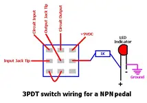
anyway i'd like to put a l.e.d. on it so i know when its on (ihave it wired so the battery is cut off when the effect is off- it works ok)

would i be able to
A: run a led in line with the power going to the effect

B: split a lead off of the switch so the led runs to a seperate ground

c: something else?


im just now getting back into circuit design and building and would appreciate any info possible,

thanks
 
Get yourself a 3PDT switch from Stew Mac, and wire it up so the first two poles are a true bypass for the effect. Hot from the battery goes to the center lug on the third pole, and then the "on" lug gets a 1K resistor to the positive side of the LED. The negative side of the LED goes to ground.


Light

"Cowards can never be moral."
M.K. Gandhi
 
did you build this pedal from a kit or from "scratch"? if a kit, can you post a URL? i need a delay pedal but haven't found one i liked yet--building one might be a nice little diversion.


cheers,
wade
 
If you got the scematic from tonepad (which is where the rebote is from), then check back there. They have a PDF that explains how to wire the board for use with an LED and switches and a whole lot more.
 
Just tap the LED into the + supply after the switch, with a resistor. If you switched the - side instead, make sure the LED drain is before that switch.
 
seismetr0n said:
isnt there someway to do it without a 3pdt?


Not with a true bypass, which you DO want. The pedal will fuck up your tone when it is off otherwise.


Light

"Cowards can never be moral."
M.K. Gandhi
 
i did get if off of tonepad... i also have their 'offboardwiring.pdf' but it too calls for a 3pdt...
heres a link to the pedal mrface2112.. http://www.tonepad.com/project.asp?id=27

i believe it is a true bypass, though its not wired like they do it..

i like mshilarious' idea.. thats what i was hoping would work.. ill just take the lead after the switched battery (9+ to efx)

ive attached a rough schematic of the switch wiring... this wiring, also shuts off the battery when the efx is not on, to conserve power (until i get a 9v power supply in there - its in a mega box- planning on adding 2 more efx in it)

by the way... this pedal kicks ass... it is a classic analog delay sound, although the 15k to 10k resistor switch mod, makes it a little too crazy.... i'm planning on putting something near a 14k in there when i add this led.

thanks all
 

Attachments

  • switch diagram.webp
    switch diagram.webp
    5.9 KB · Views: 104
seismetr0n said:
i did get if off of tonepad... i also have their 'offboardwiring.pdf' but it too calls for a 3pdt...
heres a link to the pedal mrface2112.. http://www.tonepad.com/project.asp?id=27

i believe it is a true bypass, though its not wired like they do it..

i like mshilarious' idea.. thats what i was hoping would work.. ill just take the lead after the switched battery (9+ to efx)

The LED is a very simple addition, but doesn't have anything to do with your tone and bypasses and such.

Even without a 3P switch, it shouldn't be difficult to add a buffer circuit to prevent tone loss.
 
i havent noticed any tone loss with this setup... it seems to work ok.. i will be adding the led today and will let you know if it works ok or not..

thanks
 
just an update , i added the led off of the 9+ of the switch, it works great.. with hat switch setup i dont notice any tone loss...
used 330ohm resistor..

equasion V/I=R [(9v-2.1v_led) = 6.9 / .024 (24 mlilliamps)] = 287 rounded up to 330
 
No, that's not true bypass. The input of the circuit is always conected to the guitars signal, which means it is always loading the pickups. This goes by the delightful nickname of "Tone sucking," because that is exactly what it does. If you want an LED and true bypass, it looks like the attachment.


Light

"Cowards can never be moral."
M.K. Gandhi
 

Attachments

  • switchwiringnpn.webp
    switchwiringnpn.webp
    12 KB · Views: 73
seismetr0n said:
just an update , i added the led off of the 9+ of the switch, it works great.. with hat switch setup i dont notice any tone loss...
used 330ohm resistor..

equasion V/I=R [(9v-2.1v_led) = 6.9 / .024 (24 mlilliamps)] = 287 rounded up to 330


It's not the LED that causes the tone sucking, it is the input being conected to the circuit at all times. You can also use a larger resistor for the LED to get a longer battery life, though the LED will be dimmer.


Light

"Cowards can never be moral."
M.K. Gandhi
 
so basically, the circuit is still 'sucking' some of the tone even when its turned off, becasue the input still leads to a few post resistor and cap grounds...
i think i get it
 
seismetr0n said:
so basically, the circuit is still 'sucking' some of the tone even when its turned off, because the input still leads to a few post resistor and cap grounds...
i think i get it


The pickups are seeing a different load, so they react differently. You ALSO have the issues with capacitance bleeding off highs, but that is a relatively small part of it. The big issue is the load.

Basically, the impedance (or load) your guitar is seeing from your amp is PRIMARILY set by a little thing called a pull down resistor, which usually a 1Meg resistor to ground on the input jack. Your pedal probably has one of these as well, though for a real true bypass it would need to be after the switch. The larger the mismatch between the pickups and the load, the worse the sound gets. If the load is too low, you loose low end (an extreme example of this is plugging a passive piezo pickup into a guitar amp – piezos have an impedance in the 10meg ohm range), if the impedance is too high, you lose lows. Either way, you loose dynamics, harmonics, and just generally muck up your tone.


Light

"Cowards can never be moral."
M.K. Gandhi
 
Back
Top