Radial cap in place of an axial?

  • Thread starter Thread starter sweetbeats
  • Start date Start date
So am I getting this right?

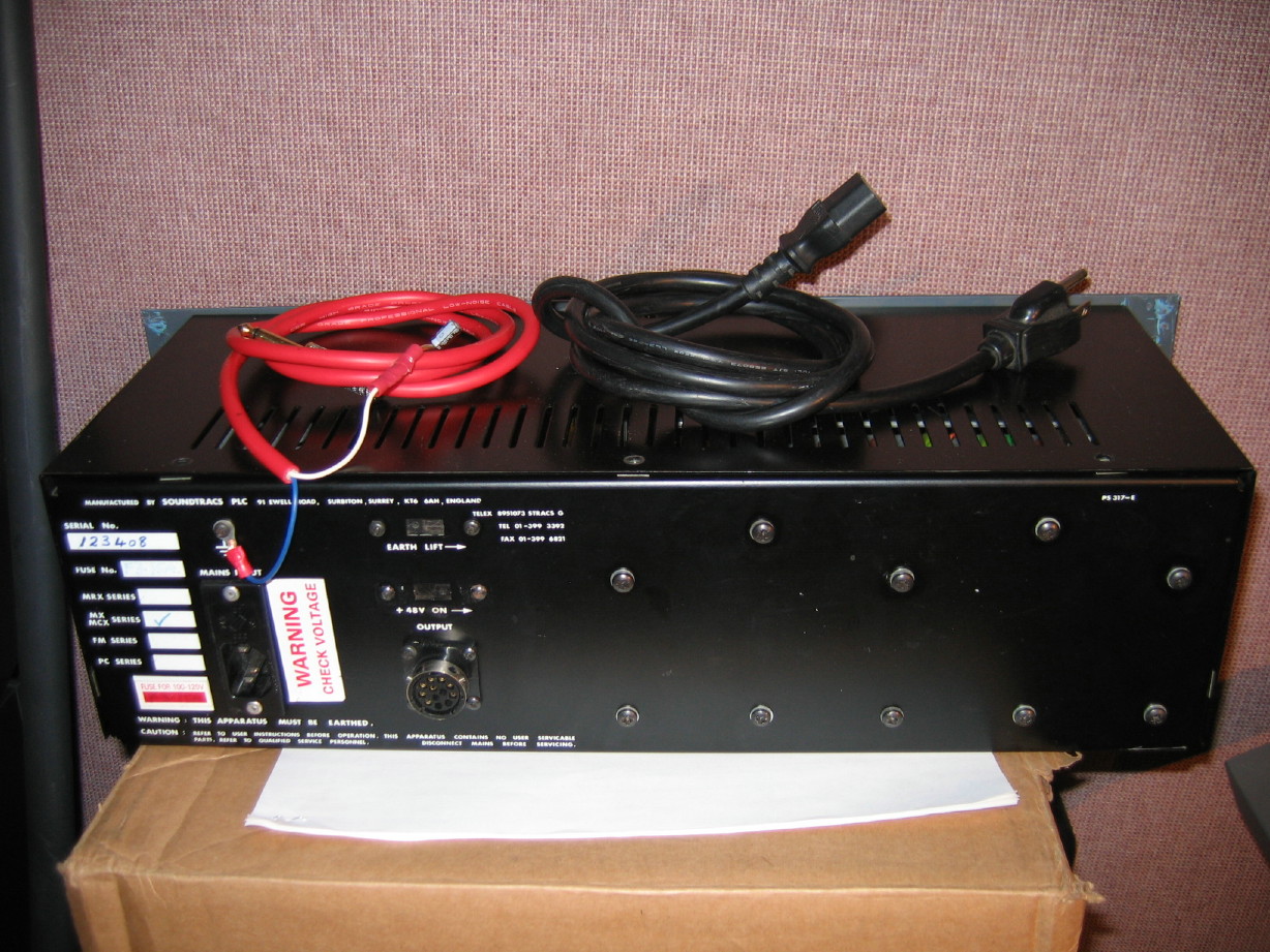
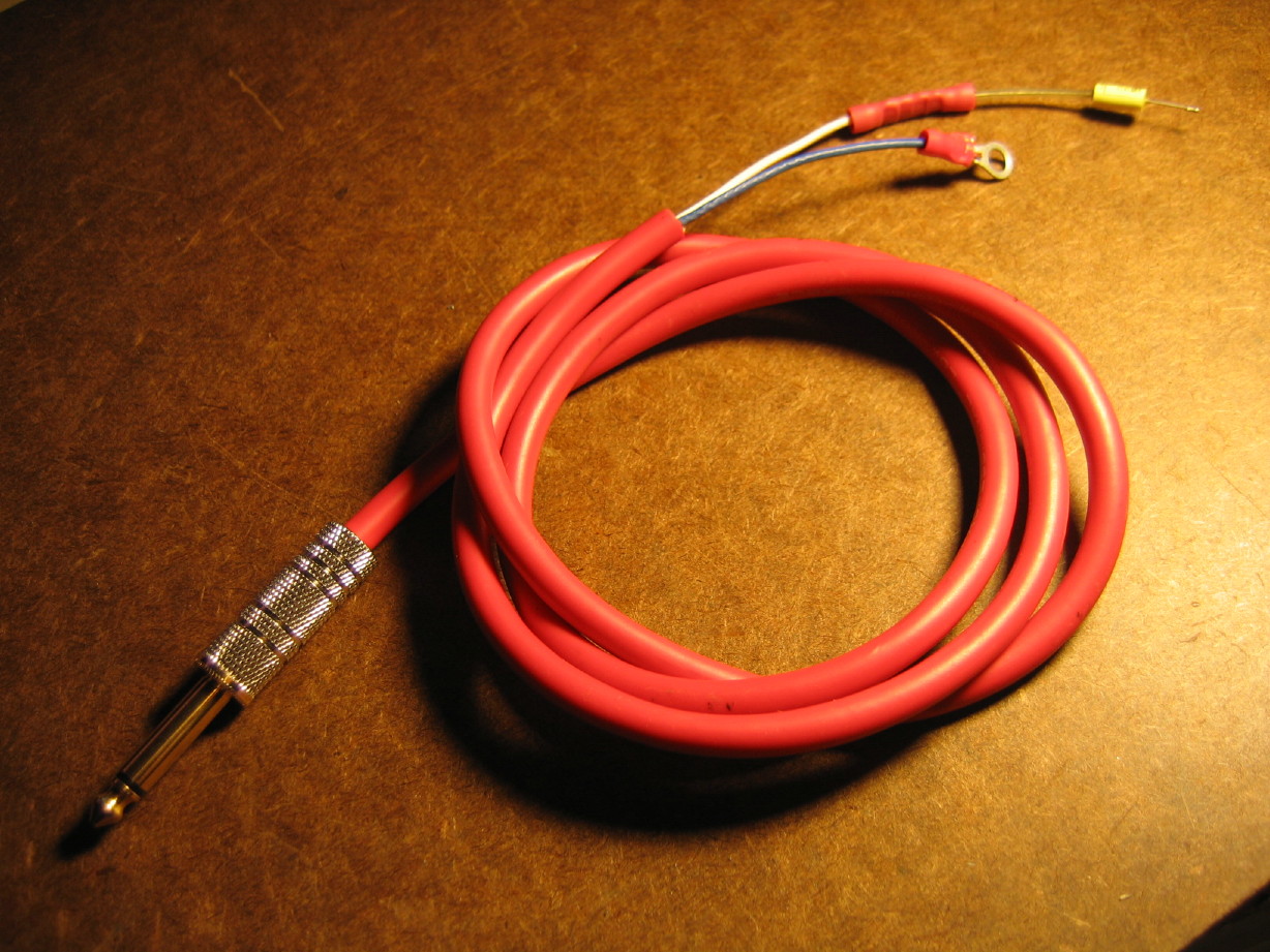
See the cable I made up to FFT the power rails...I've got a TS jack at one end with the braided copper shield of the cable and the blue conductor connected to the shield of the connector, and the white conductor is connected to the tip. At the other end the braided copper cable shield is unterminated, the blue conductor has a ring crimp on it so I can connect that to the Soundtracs PSU chassis, and the white conductor has a 0.1uF/100V film cap for a tail...THAT will connect with each DC rail one at a time for analysis. The TS plug will go into a line input on my Presonus Digimax FS. Is this correct?

IMG_6904_11_1.JPG


BTW, I got all the units patched and configured so that the input path is:

Digimax FS line input --> ADC --> ADAT Lightpipe --> Yamaha i88x --> mLAN firewire --> Yamaha 01X --> mLAN firewire --> i88x --> S/PDIF --> Tascam US-224 --> True RTA

I'd love to avoid the whole big giant loop just to get the input to True RTA, but I can't go direct from an i88x input (analog or digital) direct to the S/PDIF output...it doesn't patch that way, and another issue is that because True RTA doesn't work with ASIO audio drivers it has to be WDM and the Yamaha stuff is ASIO only for outputs to the PC...so I have to use the US-224 as the "soundcard" for Windows as it supports WDM in and out. I *think* the US-224 is too noisy for proper analysis to go direct to it...I suppose I should test that. How do I dummy-load an unbalanced input?

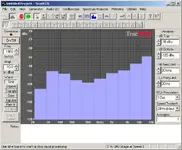
I suppose I could also just use an i88x line input and avoid a couple steps and I might try that too because there is (in my estimation) quite a bit of noise in my path, though I didn't have the input terminated on the Digimax FS. Below is a screenshot of the unterminated input via the path described above...the two lower bands were bouncing around quite a bit...not sure what that means. I'm thinking I need to get a purchased copy of True RTA...1 octave is just not cutting it...

So, please:

  1. Look at my cable and my description above of how I intend to use it...do I have it right?
  2. Comments on my input path are most welcome...
  3. How do I load an unbalanced input?
  4. What do you make of the screenshot below? Is the noise floor too high to do an effective analysis of the power supply rails?
 

Attachments

  • screenshot.webp
    screenshot.webp
    39.7 KB · Views: 97
Honestly I can't follow your setup, it's too confusing. However, 100nF into a 10K line input won't work too well, that's a 160Hz corner. Ideally you have a really high input impedance amp, an instrument input should work better than a line input. Then you could keep the 100nF cap. You don't need to worry about "loading" an input (that's backwards really), the PSU impedances will be quite low on account of their caps. Instead, the PSU is a "signal" source that you need to keep unloaded to get a useful measurement.

In related news, I opened up an RME unit to troubleshoot a bad channel, and it had a switching PSU (looks like something they bought, not built) that has 400uV ripple. As appalling as that sounds, it's not the source of the problem, most of the channels work just fine, and the unit has 113dB dynamic range . . . I did not analyze the spectrum, since normally I would use the RME to do that, but it's possible much of that noise is out of the audio band anyway. Or not. But that's a pretty good demonstration of an IC's ability to reject power supply noise.
 
Honestly I can't follow your setup, it's too confusing.

Awesome. That makes two of us then. :D No sweat. I understand.

100nF into a 10K line input won't work too well, that's a 160Hz corner. Ideally you have a really high input impedance amp, an instrument input should work better than a line input.

Okay. I'll use the instrument input on the Digimax FS then...1mOhm input impedance.

You don't need to worry about "loading" an input (that's backwards really), the PSU impedances will be quite low on account of their caps. Instead, the PSU is a "signal" source that you need to keep unloaded to get a useful measurement.

I understand. What I was asking about though was for the purpose of testing the self-noise of the input path starting at the input jack (no DUT connected yet). Back a few posts ago you suggested I check the noise levels of the mixer. "Terminate all inputs at 150 ohm..." Am I using the wrong term when I say "load"? I mean "terminate". How do I do that with an unbalanced input?

In related news, I opened up an RME unit to troubleshoot a bad channel, and it had a switching PSU (looks like something they bought, not built) that has 400uV ripple. As appalling as that sounds, it's not the source of the problem, most of the channels work just fine, and the unit has 113dB dynamic range . . . I did not analyze the spectrum, since normally I would use the RME to do that, but it's possible much of that noise is out of the audio band anyway. Or not. But that's a pretty good demonstration of an IC's ability to reject power supply noise.

Okay. Thanks for the perspective. Just want to get a baseline here so I can do before and after comparisons on the PSU.
 
FFT results

Well, I cut out some of the steps in the input path to try and get as clean and simple a path as possible.

The final path was:

  1. i88x input #1 set to Hi-Z
  2. ADC
  3. i88x channel #1 digital direct out via mLAN firewire to 01X channel #9 digital direct input
  4. 01X channel 9 to "REC BUS" (this is a simple secondary stereo buss that seemed to be quieter than signals routed through the main buss)
  5. 01X "REC BUS" routed to S/PDIF out to...
  6. Tascam US-122 S/PDIF in to True RTA

Here's what True RTA revealed of this input path with the input unterminated:

unterminated_input.jpg


Now, here is the +48VDC rail:

+48VDC.jpg


Here is the +24VDC rail:

+24VDC.jpg


Here is the +17VDC rail:

+17VDC.jpg


And finally the -17VDC rail:

-17VDC.jpg


Comments?
 
What's the dBFS to dBu calibration? I mean they label that dBu, but I'm guessing it's really dBFS. The spectrum looks usual, even at that very low resolution, basically white with a bit of 60Hz hum. Integrated noise would be ~40dB higher than spectral noise, so if I take a wild guess that +20dBu = 0dBFS, that means noise is -60dBu (1mV). That does seem higher than it should be, so I would investigate your methods further. I'd especially like to verify that calibration, and obtain a better resolution FFT so I could see if that is truly white noise, or just a lot of induced hum throwing off the measurement.
 
Okay...yeah...

So I went ahead and purchased the 1/3 octave version of True RTA so that will give some more depth to subsequent analyses, and, silly me, I didn't calibrate the I/O of the analyzer software...it has utilities to do that, though it may get sticky since I'm using the S/PDIF input of the US-122...not sure how that compares relative to the analog I/O since I have to monitor the output with a true RMS meter while calibrating ('Y' cable etc.)...I'll have to figure that out, but bottom line I'll get some specificity to the scale.

Also think I can take another link out of the input xhain as I haven't tried just going direct into the 01X instrument preamp...I assumed it would be noisier as the mic pre's are noisier, but it may be a wash being able to remove another link in the chain so I'll check that out too.

Thanks!
 
True RTA can't be calibrated when using the S/PDIF I/O...that's a bummer. Don't know why they wouldn't design in an ASIO component to the software so it can utilize ASIO hardware I/O...:mad:

So I fear I'm going to have to get ahold of a cleaner analog WDM interface for when I'm using True RTA...here is the terminated instrument input on the Tascam US-224 after calibrating the input and output...connected to the Soundtracs MX +48VDC rail output but the PSU is off, and the other end is connected to a Hi-Z input on the US-224:

terminated_input_PSU_off.jpg


As I mentioned above, I calibrated the inputs and outputs...here is what a -10dBu 300Hz sine wave looks like when produced at the US-224's line output and terminated in one of the instrument inputs. Output level trimmed to about 1:00 which yielded 245mVAC RMS and input trim at MIN, but True RTA compensates, so as you can see its doing what it should:

-10dBu_300Hz_sine_wave.jpg


Here is the +48VDC rail:

+48VDC_rail.jpg


+24VDC rail:

+24VDC_rail.jpg


+17VDC rail:

+17VDC_rail.jpg


-17VDC rail:

-17VDC_rail.jpg


So, yeah...I'm thinking I need a cleaner input path and using a line level input would help that, so I need to change that cap out. What should I use there?? Type and value??

Comments?

Thanks for the help. This is valuable.

[EDIT]

Also, I measured the AC ouput of each of the above rails with my Fluke meter and each was about 0.1~0.2mVAC.
 
Well the RTA and RMS measurements seem consistent at least, but again, a truly quiet supply would be 10x better than that--but does it really matter? Again, my RME box is 6dB worse than your mixer, but it can still measure an input noise floor of -108dBV. Now, converters get life easy, because they are line-level devices; a mic input has to be 20dB better than that. Just be aware that ICs with better than 60dB of PSRR are going to deal with problems like this.

The next thing to consider is you can't improve power supply noise much by swapping caps or doubling bulk capacitance where there is already 3300uF on the rail. If there is a problem with ESR, you parallel a ceramic cap.

Generally, it's far more effective to add another RC stage. Probably I would worry most about the phantom rail, because it's the easiest to fix, and if some microphone doesn't have correctly matched impedance on each pin, you'll get that noise injected straight into your audio. Such mics aren't common, but they do exist.

It's easy to define phantom current: 32 * 10mA = 0.32A. That across 10 ohm is 3.2V drop, which keeps us in spec (min 44V) at maximum load (highly unlikely). So a 10 ohm / 1000uF RC stage will make a more dramatic improvement than 3300uF paralleled with the existing cap.

The IC rails are tougher because current is probably higher and even a 1V drop wouldn't be tolerable. But I would try maybe 1 ohm. I've also used an LC circuit to get larger improvements but I don't know if that is advisable here. Tricky as there will be a resonance, but a bit of resistance inline might be enough to prevent troubles.

Don't forget to take a measurement of all-channel audio path noise before you start modding . . .
 
Thanks, msh...understood.

What value cap and what type of cap should I strap in between the PSU rails and my test cable if I'm conneccting to, for instance, a 10kohm line input? 0.01uF? Any film cap will do?

The advisement I'm getting on the upgrades is that the noise is a manifestation of poor conductivity in the mating of the filter caps to the PCB, relatively noisy bridge rectifiers and regulators and poor heat management. So better parts have been spec'ed and, just to be clear, I have not been advised at any point that making changes in the filter cap spec is a priority...bottom of the list. The focus is better conductivity via changes to how some key areas were soldered as well as some changes in wiring, better spec rectifiers and regulators, and much better heat management...adding some heat sinking and relocating a couple parts...better insulators too.
 
No, for lower impedances you need larger caps, not smaller. 10uF ought to do; use an electro.

The advice about replacing the active parts is probably good; it's down to the regulators to suppress most of the ripple, a good regulator will do a lot more than more capacitance.
 
Cool...thanks.

10uF caps I have. :D Lots.

OH!

HAHA!

But only one that will work at least within my comfort zone...everything I have is no more than 50V except for ONE 100V cap...now to see if I can FIND it...heheh...
 
I wouldn't worry about that, unless you plan on testing the transformer primary. Caps are rated for voltage AND temperature, so it's not like it will suddenly explode at 51V and room temp.
 
Right...okay. Regardless I'm just paranoid.

So here are the final screenshots before diving into this thing. I must say that I'm pretty pleased with the noise performance as-is but I'm going to go forward with the mods on the PSU for a couple different reasons...I already have the parts and instructions here, IMHO the stock heat management is pretty sad, and in the end the mods couldn't hurt. :rolleyes::D

So these screenshots were taken using the US-224's line input...

unterminated calibrated input:

unterminated%20line%20level%20input.jpg


Terminated input (connected to PSU but PSU switched off):

terminated%20line%20level%20input%20to%20psu,%20psu%20off.jpg


+48VDC rail:

+48VDC%20rail.jpg


+24VDC rail:

+24VDC%20rail.jpg


+17VDC rail:

+17VDC%20rail.jpg


-17VDC rail:

-17VDC%20rail.jpg


Okay. All pretty boring AFAICT.

Here is an FFT of a main output passing system noise. As advised, all 32 mic amps are terminated with a 150ohm dummy loads, the mic trims are at max, the channel faders are at unity, the master faders are at unity...I measured 2.5mV with my Fluke meter at one of the main outputs:

32ch's%20open,%20main%20out.jpg


2.5mVAC RMS equates to about -49dBu...the FFT graph doesn't show that but I'm assuming that the way the meter reads voltage is some complicated summing of the audio band.

So I see line noise there but this was done in a room full of flourescent light fixtures. STILL good IMHO for having 32 mic amps open and trimmed to the maximum gain.

Here is the same thing except instead of having all 32 channels routed only to the main buss I also routed each channel to all subgroups, set the sub faders to unity, set the prefader level pots to "7" and dumped the subs to the main buss. Great way to make noise...about 9mVAC RMS of noise...did better than I thought it would:

32ch's%208gp's%20open.jpg


After doing these tests the back of the PSU was quite hot...no finned heatsink on this thing and that does not seem right. The mods will cause more dependence on that rear section for heat dissipation so I'm going to go ahead and add a finned sink using the two reel motor sinks from a Tascam 48 I parted out last year. I'll have to have a friend of mine shave off two fins on one of them, but then this thing will actually fit really nice and should help.

Rear view of stock supply:

IMG_6920_3_1.JPG


Annnd the as of yet unmodded fins, but this will give you an idea of what it will look like:

IMG_6921_4_1.JPG
 
The results...

Well, I wish I could do an FFT comparison but I'm having issues with True RTA not outputting tone...I'm pretty sure it is a driver issue for the interface, but I can't find my USB key with all my drivers and licenses on it...arg.

You don't care about that.

So it'll have to be a comparison of the noise measured via my voltmeter at one of the main outs.

32 mic pre's dummy loaded @ 150ohms; all mic trims at max; channel faders at unity, all channels routed to the main buss; main faders at unity:

Before: about -50dBu
After: about -53dBu

32 mic pre's dummy loaded @ 150ohms; all mic trims at max; channel faders at unity, all channels routed to the main buss and the 8 groups; main faders at unity; group faders at unity; group level to main buss at "7" (about 2:00):

Before: about -39dBu
After: about -43dBu

If I repeat the first test but reduce the mic trims to a more normal position (about the 2:00 position) the noise level is about -64dBu.

Again, this was measured at only one main out jack...can't recall what the effect would be if measured at both simultaneously...

Anyway, those are significant changes yes?

And the fringe benefit is that, whereas before the back of the PSU became nearly too hot to touch, it is now just pleasantly warm with all my heat dissipation mods.

[EDIT]

Another fringe benefit: before I was getting this crazy feedback oscillation with the second test if I took the levels of the groups to the main buss past about 3:00...like a 7Hz pulsing that would grow and grow until I muted the groups. Doesn't do that now...Now I can take that second test scenario and max everything (trims, faders, level pots all maxed) and she's steady...noisy of course, like -6dBu :rolleyes: :D, but it can handle that which will, um, come in handy...NOT!
 
Yeah, 4dB is quite worthwhile. I am surprised about the stock heat problem; that does sound underengineered . . . and the oscillation could be a problem of inadequate bulk capacitance. Well done . . .
 
Back in the day (early 90s), Sony receivers were notorious for voltage regulator transistors in their power supplies getting extremely hot, causing the solder joints to heat up enough to become defective. As a fix, I would mount them on the rear panel and run wires to the circuit boards. Never had a repeat repair on one, although I did perform this mod on several repeat repairs where other techs had simply resoldered the connections.
 
Thanks for the comments and affirmation, gents.

LDS, yes, improving the contact area of some key solder joints was part of the upgrade, as well as relocating the bridge rectifiers and connecting via wiring vs. through the PCB.

msh, yeah, it is a little disconcerting how the heat management was designed as stock. I'd like to think it an oversight as I like how the rest of the system looks...oh and that heat level was from JUST the regulators as the rectifiers had a very plain aluminum bar mounted to them...just not enough. Everything is on the back wall now with that nice finned heatsink just on the other side...no more self tapping screws but all stainless 10-32 machine screws cranked nice and snug with GB hi-pro compount between everything...I paid attention to how things were spaced to so that one component's heat shed didn't crowd into another.

The oscillation...maybe I'm misunderstanding you but I didn't increase the capacitance...still dual 3300uF caps. The voltage rating is higher...thinking back its almost like the mixer was getting starved and maybe that was the old regulators not keeping up? Or the rectifiers for that matter. They were kind of wimpy.

Anyway, all in I think it was well worth the nominal fee I paid for instructions and 1:1 tech support/guidance, and that is ongoing into other areas too.

Thanks for all the help here. I really appreciate it!
 
Back
Top