Radial cap in place of an axial?

  • Thread starter Thread starter sweetbeats
  • Start date Start date
sweetbeats

sweetbeats

Reel deep thoughts...
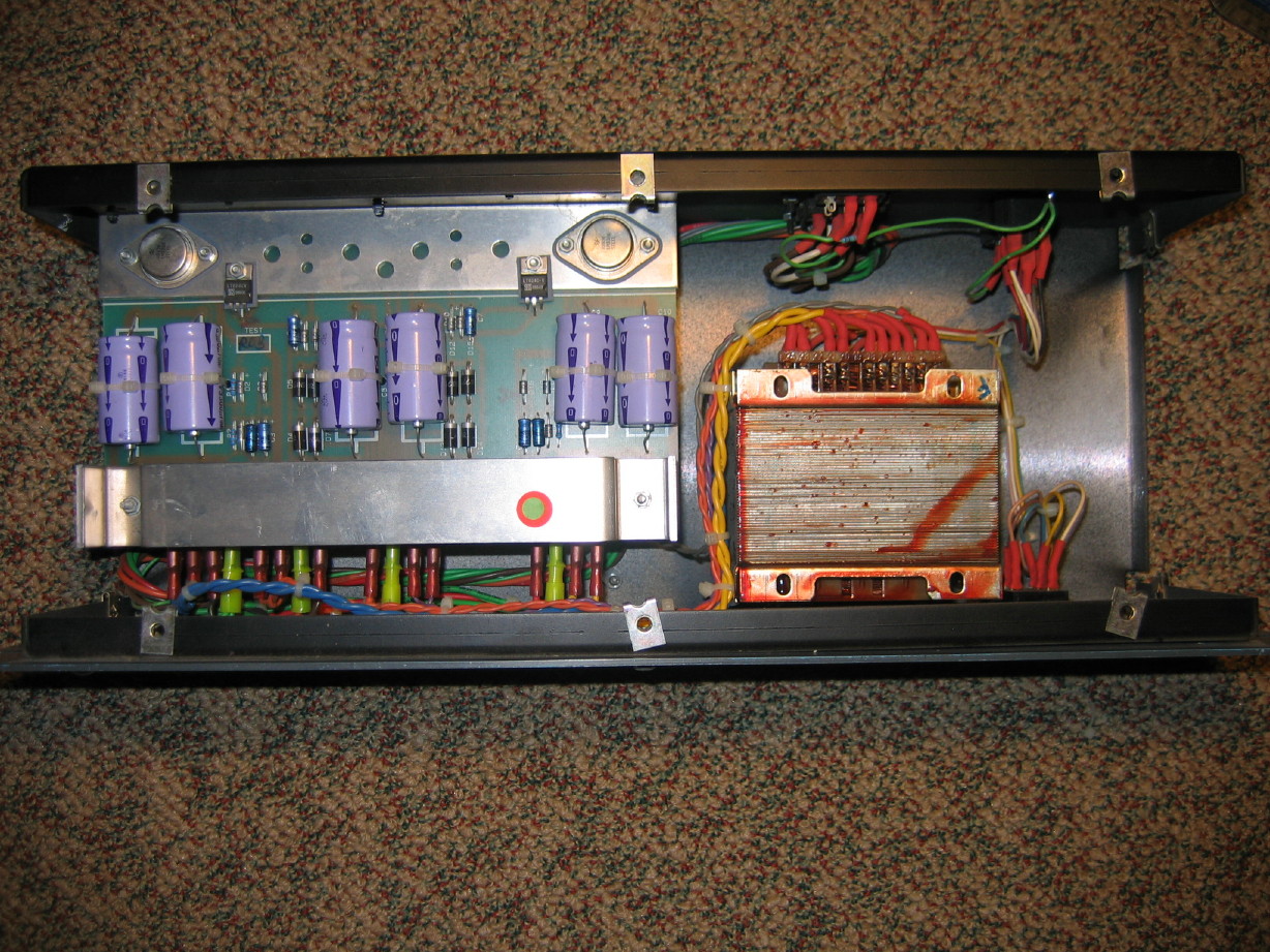
I want to recap the PSU for my Soundtracs MX mixer. There are 3 sets of filter caps in the PSU, all 3300uF/35V caps, and all axial termination. Hard to find anything in those specs in axial for a reasonable cost and nigh impossible in anything larger if I want to find it in stock anywhere. There is PLENTY of space, so I'd like to increase the value. The pads are about 2 1/8" apart. Any caveats for just getting radials and spreading the leads apart? No other traces or pads on that side of the PCB so I'm not nervous with lengths of unprotected leads...I was going to adhere the caps to the PCB with RTV and call it good. Any comments or suggestions are most welcome.
 
Depending on the tracking of the board, and vertical space, it may be possible to drill one or two holes and mount the RB cap in its more normal vertical mode. The pigtail leads are then run across the underside of the board. Usually looks neater. We usually use hot-melt glue to adhere caps to the pcb.

If laying them flat on top of the pcb, it's still considered good form to put spaghetti over the exposed flying leads.
 
I was going to have them upright on the same side of the board as they are at present, spread eagle. Here is the board. Not sure if there is clearance underneath...

IMG_6875_9_1.JPG
 
If you're going to stand them upright, and run the pigtails across the top of the board, just be careful that the pigtails don't cut through the plastic insulation on the body of the cap. Heat from soldering can cause this to happen.

Looking at your photo, I'd be inclined to lay them horizontally side by side, and rotate them 90 degrees, so that the pigtails from one capacitor are at the top end of the other capacitor. Hope that makes sense without doing a drawing.
Assuming it wasn't possible to drill new mounting holes, which would be my first preference.
 
Mouser:

140-XAL35V3300-RC

If you want to increase value, use two. Do you need to increase value? Unless Soundtracs really screwed up, you probably won't decrease ripple very much more. The regulators ought to be managing that for you, if the circuit is well designed.
 
I want to recap the PSU for my Soundtracs MX mixer........

You want to, or you need to? I'd think the regular axial types would be so common, but maybe where you live they aren't. I would probably find 4700uF/35VDC around here just by closing my eyes and swinging a dead cat. Maybe I'd have to settle for 50VDC, but I'd find something.
If you have an ESR meter, test the original capacitors. Then measure capacitance. If the mixer isn't humming away, I may just leave the originals alone. Hopefully this isn't just because someone told you that old capacitors have to be changed for some voodoo reasons.
 
msh and ranjam, it was recommended to me to replace the stock caps with caps of higher value and low ESR to "increase reliability and lower noise". That was from Steven Magalnick who is the North American rep and support guru for Soundtracs mixers. He's represented Soundtracs for a long time and has worked with mods in the PSU's and in the mixers. He's been very helpful and available thus far, hence why I took stock in his advice about the filter caps in the PSU.

There are 12 caps total in the PSU and I've just made it a habit in a larger piece of gear that is pushing 25 years of age (and with an unknown history) to recap the power supply as cheap insurance, so that's my rationale. I'm not planning on messing with the caps in the rest of the mixer unless an issue calls for it.

Commanda, thank you muchly for the advice. Looks like there is room underneath or above so I'll consider both options. It is a 3U case and the PCB is just about in the middle vertically.
 
OK, recap 25 years old, fine, but there are still 3300uFs you can buy, such as I linked. If you want to decrease ESR, parallel with low ESR caps (small value ceramics are usually used for that purpose). But will the regulators be stable with very low ESR? Some aren't, so then you put a ceramic on a second-stage filter after a small amount of series resistance.

Also, if this is an IC mixer, the ICs should have pretty decent PSRR, if not then I wouldn't bother with the mixer in the first place. Seriously, if 12x 3300uF can't quiet down a power supply, you should look towards the regulators, because if they aren't quiet or fast enough, that is a much more effective replacement than dumping tons of bulk capacitance at a problem.

Article on this topic:

http://www.national.com/nationaledge/jul02/article2.html

Summary: good regulator design is a better solution than lots and lots of capacitance.
 
Msh, thanks x3.

I appreciate the article and will read it straight away.

The other piece of all of this is that I'm paying a small fee and getting some instruction and support specific to this power supply to upgrade the regulation. The mod is field-tested and has typically resulted in a 6~12dB drop in the noise floor. I've gotten the sense that the regulation wasn't the best in the first place and that the mod takes a big picture look at the regulation AND filtering as a whole. I'm thinking this is coincident with your advisement. Found some Vishay 3300Uf/40V axials at Mouser and I'm going to see if those partner well with the upgraded regulation.

I'm familiar with the filter cap bypass ideology. I've done this (upon advisement of folks at the Ampex List) in one of the 39VDC supplies for my Ampex MM-1000 tape machine. The 39VDC supplies power the amplifier electronics. The main filter cap is a 2400uF/200V cap that I bypassed with a 0.1uF film cap (IIRC) for this very reason. No opamps in those electronics. The mixer has a discrete transformerless mic pre but the eq, aux busses, group drivers and summing are all opamps. 074's for eq and 5532's for auxes, groups and summing (I *think*...schematics on the way but that's how the PCB looked...)
 
Okay...read that article. Mostly over my head, but I believe I understand the overall premise and it has sparked some good questions regarding the regulator upgrade.
 
Probably so. I have to say that if improved power regulation and filtering makes a 12dB difference in noise, then the original product was very badly designed. I can't think of an excuse for that, really.

If you are paying a fee, I would measure noise before & after the mod. Terminate all inputs at 150 ohm, crank the gain to max on all channels, set all other controls at unity and see what you get.

Oh, and the jist of that article does not support the "filter bypass cap" ideology. First off, you normally don't bypass filter caps with polys, you would use ceramics. The poly bypass cap is an audio path technique, which Cyril Bateman's work shows to be specious. And it's critical to evaluate whether very low ESR will help or hurt with the regulator in question. Willy-nilly bypassing could make matters worse.
 
Suggestions on how to terminate 32 mic pre's with a 150ohm load? Do I actually need to strap resistors across, uh...pins 2 and 3 of all of them? Wait...no, um...urg...

And the mod on the Ampex PSU was under direction from Rick Chinn and wasn't willy-nilly. I totally get your point. the more I learn the more wary I get of doing ANYTHING. I think the bypass mod was under advisement also from the Larry Miller who was a or the principle project manager for the Ampex 440.

Also, I do believe one of the criticisms of the Soundtracs M-Series was the noise floor. That would (in my mind) support a design issue.
 
Well, Rick Chinn does know what he is doing, but I imagine his advice was specific to that circuit, or at least that type of regulator, rather than being an ideology. It's always worth reading the datasheet of the device in question. For example, pg. 9 of the LM317 datasheet mentions ripple reduction by adding a 10uF cap in the feedback loop, that will be much cheaper, smaller, and more effective than doubling output capacitance (assuming the reg is an LM317, which I don't know at all, so check the datasheet for your device).

Also, noise (should be) a function of the audio circuit itself. A discrete front end should be quiet; if it isn't; it probably needs to be redesigned. It is possible for a discrete design to have poor or no PSRR (but that shouldn't have happened). The ICs in question have their own input noise; I think 8nV/rtHz for 5532 and 18 for 074, but that's off of memory so I could be totally making that up. But those come after the input noise, so they shouldn't matter much really. And again, those chips have enough PSRR to cope. It will be interesting to see where the reduction is realized (for example, if you bypass the pres by tapping the inserts, do you still get reduced noise?) But yes, you'll have to terminate all inputs to measure that, or at least say eight of them (then don't use the other channels in the noise test).
 
Well, Rick Chinn does know what he is doing, but I imagine his advice was specific to that circuit, or at least that type of regulator, rather than being an ideology.

100% agreed and that's what I intended to convey if I didn't.

So:

  1. strap 150ohm resistors across pins 2 & 3 OR across pin 1 & 2 or 3?
  2. GAIN to max
  3. EQ and PAD off
  4. ASSIGN each channel to the L-R buss
  5. fader to unity
  6. master faders to unity
  7. measure output at master jacks with a true RMS meter set to AC volts?
 
Talked in-person to evm1024 and thus answered my question regarding the load strapping: pins 2 and 3...
 
Fairly standard stuff, like the PSU in practically every similar mixer. Note the caps in the feedback loop I mentioned, so I'd be surprised if this supply was really noisy. If it still is, then it can be helpful to add an RC stage rather than just another cap, say 1R for the R and another 3300uF for the C. If that's too much drop, shrink the R.

Notice how there isn't the same love for the phantom rail as the ICs . . . everybody assumes that phantom noise is canceled by input CMRR, but not all mics have perfectly matched impedance to ground. And of course the PSRR of the ICs is really good. Anyway, that's just my soapbox, because I have seen noisy phantom rails cause problems, and the phantom rail is probably 10x as noisy as the +/-17V here.

What's the +24V for?

Tell you what you need to do is just measure the noise on the power rail directly, or better yet do an FFT on it. Some O-scopes can do that, or actually audio converters & analysis software are quite good at it too, just be sure to couple to the ADC across a cap. If the power rail noise is less than -100dBV (10uV), then I'd call it a day. Heck, anything south of -80dBV should be OK into an IC, that discrete stage though I dunno.

I'd be using either a Presonus Digimax FS or Yamaha i88x for ADC...probably the former...I seem to recall there was more noise in the Yamaha. Anyway, and True RTA for analysis.

The 24V rail is for the meter arrays.
 
Without looking, the FS is probably 0dBFS = +15dBV, and has ~110dB of dynamic range, so noise floor would be -95dBV. If the power supply is in that neighborhood, it should be fine.
 
Arg.

True RTA's I/O is linked to Windows' system defined audio input and output...this would be no big deal except that my Yamaha ASIO mLAN drivers don't accommodate recording through the Windows system. They accommodate playback (i.e. Windows Media Player will play through the Yamaha hardware, but Windows can't see the Yamaha hardware's inputs).

My Tascam US-224 analog I/O is too noisy to use but it has S/PDIF I/O and Windows can see both inputs and outputs of the 224...I'll have to use the Yamaha 01X and i88x as well as the Presonus to make this work just so I can FFT the thing:

Presonus input --> ADC --> i88x (via lightpipe) --> 01X (via mLAN IEEE1394) --> 01X S/PDIF out --> US-224 S/PDIF in.

:eek:

I'll have to FFT THAT with the input dummy-loaded to see if all that will still allow a useful analysis of the power rails.

What a PITA.
 
Back
Top