A
AnalogApples
Active member
 Find a Cure for GAS
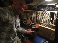
I bought this old 24 channel Neotek Series III last winter. It had been stored in a garage for 10 years. I got a really great deal on it. Then I discovered that due to the humidity in the garage, the seals on many of the electrolytic capacitors are failing. Mike Stoica told me this is what's happending since it was stored in high humidity. It has many problems which would be explained by having all original capacitors that are failing. Even the IC chip legs have black gunk on them from the moisture.
I've ordered 858 capacitors off of Mouser. Most of those are going obsolete once their stock runs out.
Since I'll be desoldering about 2,000 wires, and resoldering about 2,000 wires, I'm now worried about hysteresis between the capacitor wire and the solder pad. Solder apparently is MUCH less conductive than copper. Which means, if I want to do it right, my capacitor wires must be physically touching the pad while I apply solder. I cannot just feed the capacitors in, and fill in the holes with solder. I think it'll take me much longer to replace all the caps this way, but maximizing wire to copper contact before applying solder is the best way to do it. I'll be literally tugging on the capacitor from one side of the board while I apply solder. I'm going to buy some Cardas audiophile type solder which they claim is best for audio. It's $45 for a 1/2 pound.
Does anyone have any thoughts about this or anecdotes about professional recapping jobs on large consoles? Did you guys just feed the caps through, then solder the hole and clip the wires, relying on the solder to connect the component? Or is it standard to completely clean off the pad, then bend the cap wires to make maximum contact with the pad, then tug on the cap to keep it tight against the pad while adding solder?
More details about the mixer: I have a couple of channels that were in the master section but never reinstalled. I can see piles of river silt sitting on some of the components, and on the meter bridge. I think this thing may have been underwater at one point. It's a new power supply, and 19 out of 24 channels are working. My goal is to recap all 24 channels, and the meter bridge, and see where that gets me. Then I only need 2 more parts to rewire it in it's original configuration (I need the master channel, and the meter select channel) It's been a fun, very rewarding project!