More Tascam 388 woes

bobob

New member
Hi all,

My 388 has developed a fault, wondered if anyone could offer some guidance.

The transport started acting a bit strange, play would only engage if I held down the play button for a few seconds, and now the transport is completely dead.

The number display is still lit, but none of the control buttons work. Motor is still turning when powered on. Vari speed etc all still work, it’s just the play, record wind buttons etc.

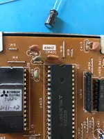
Does this sound like the eprom? I’ve found a freshly flashed replacement, just wondered if anyone thinks the problem might be elsewhere?

Thanks.
 
Unfortunately not, no. It's like the buttons are completely unconnected. Traced the power as much as I can and it seems to be ok, but I'm a bit clueless when it comes to testing the functionality of the chips on there.
 
Bit more on this, when testing the oscillator at Y400, it's not giving a clear reading. Also it seems to be clicking in the mechanism for play sporadically when touching with the multimeter. I don't know whether that's because it's failed, or it's something else causing it.
 
Last edited:
“Oscillator at Y400”…can you provide some more detail? What PCB and what part? I’m not familiar with anything designated Y400 in the guts of a 388. Maybe post a pic of the component?
 
It's the control pcb. It's labelled Y400 in the manual, it's CR400 on the board. The 6Mhz resonator. Hang on, will get a picture...
 
It's on the control pcb assembly, mounted under the transport buttons.

It's the one labelled CR400, with the white 6MHZ printed above. It's labelled Y400 in the service manual.
 
Thanks. Weird. “CR” is a designator for a diode on some assemblies so that’s what threw me that the PCB shows “CR400”. I see now in the service manual the “Y400”.

So IC microprocessors are out of my wheelhouse. What I can say is Y400 is strapped across pins 2 & 3 of U403, which is an 8-bit M5L8039 microprocessor; datasheet here: https://happytrees.org/files/chips/datasheets/datasheet-Mitsubishi--M5L8049--M5L8039.pdf
Pins 2 & 3 are the clock reference inputs to the processor, and likely when you touch Y400 with your meter probes you are increasing the capacitance and probably changing the frequency of the oscillation. That probably makes the processor do stuff. I really can’t say if this is normal or not. Maybe somebody like @jpmorris might have some better insight. I’m sorry I can’t help more.

Have you verified that the +5V supply is working correctly? That is critical because dirty power or incorrect voltage will wreak havoc with logic and microprocessors. I recommend you verify with a scope all power rails at the control PCB are clean and correct before doing anything else.
 
Thanks @sweetbeats. I'll check the power rails again tomorrow, but it seemed ok when I did it over the weekend. Will double check again.

Already tried swapping U403 out, but still the same.

Think this might have been caused by a short. I noticed when I opened it up that the pad had lifted on pin3 of P2 on the mechanical PCB assembly. Didn't look like it was touching any of the other pins, but it may well have done with the clunk of the tape etc. So it might have shot 35v down somewhere to the control PCB assembly.

Could be wrong and it's nothing to do with that, but thought it's worth mentioning.
 
Just with a multimeter, I haven't got a decent oscilloscope unfortunately. Got a cheapy one I'll try with tomorrow.
 
Yeah the multimeter will show you the voltage, but what it can’t really do well is to show you if there’s any AC dirt on the DC rails, pointing to bad filter caps or a bed rectifier…unless it’s really bad. This all depends on the multimeter of course, but it’s way easier and more reassuring to be able to actually see the AC ripple if it’s there, visually verify the frequency and source as AC line ripple and really see the amplitude. And then to do this all under load. I had a situation with a device recently where there was 120Hz hum in one channel of the stereo output when I engaged the processing circuitry. When the processing circuitry was bypassed there was still a little hum but barely noticeable. I isolated the power supply and everything looked great. Which sent me on a short goose-chase. Then I thought to scope the rails under load, and sure enough when I loaded the bipolar supply with the processing circuitry the -15V rail crapped out causing all sorts of heinous DC offset no amount of CMRR could deflect…I replaced the rectifiers. That wasn’t it. I was about to replace the LM3x7 regulators when a friend of mine caught a comment I made about the size of the main filter caps…470uF…the device is a multiband dynamics processor…a fair amount of active devices. The capacitance of the -15V rail main filter had drifted enough that the filter could no longer keep up with the filtering. The part was just barely enough when new, but now with the drift the time constant came up short. The cap was still in spec, but was lower value than the +15V rail filter, which is why that rail was fine…for now. I had already planned to replace the filters with 1,000uF parts…that fixed it. But the scope was really essential in helping me see where the wave wasn’t right at different points in the supply. I didn’t have the knowledge to fix it once I got stymied…my plan to shotgun the filters with upgraded parts would have fixed it, but my friend educated me and it was easy at that point because the scope revealed all the necessary clues.
 
Back
Top