RICK FITZPATRICK
New member
Howdy guys. Its been a long time since I posted anything. So here goes.
I recently picked up these panels.
http://Stingrayproductions.net/GIFs/RMFstudio/Modelpics/insulation5.jpg
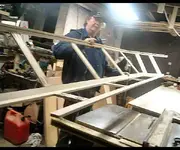
Ok guys, the point of this post is to illustrate my latest project. Namely, to utilize the materials I have to their best advantage. Once I had the materals, then I began building a fullscale cardboard "mockup" of one 24"x 72" x 4" thick panel, used across a wall/cieling corner. Trouble was, it was difficult to relocate it, as well as visualize what it is I REALLY wanted this to look like in the studio. Not only that, because of the geometry of my room, there are no wall/wall corners to utilize "superchunks", except at the rear closet, which is the point of my another upcoming thread titled "Rear Wall Options". And I've decided to use the closet for a Skyline diffuser, although there are areas that could be filled with 703, but at this time, I'm more interested in using what I have for the rest of the room. The other problem was DESIGN. Folks, I've been a designer for many years as well as a CAD detailer/draftsman. And for the last two years I tried to visualize what it was I wanted in the way of "treatment", at the front, sidewalls, and cieling. For four years I've been fortunate enough to run across forums such as this one, whereby I've been able to grasp a few concepts for treating a room acoustically. But visualizing something in 3D in Autocad leaves a lot to be desired. I even tried a few 3d programs suich as Sketchup and Rinocerous, but haven't found a way to convert the file format extention to something i can post on the net. Even then, the 3D programs really DIDN'T allow for visualizing a space from INSIDE the space. At least from what I knew I wanted to see. Thats when the idea to build an actual model, instead of a virtual model. Hence this post.
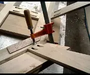
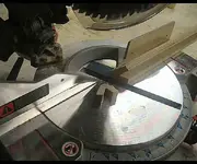
The first thing I had to determine was scale. Since I had about 20 rigid fiberglass cieling tiles, and they were 1/2" thick, I determined I could scale the 1/2" to equal a 4" thick panel of 703. This works out to 1 1/2"=12". Perfect size. Once I had my scale, I gathered a bunch of materials. Since my wife sells on ebay, we have a ton of packing materials to chose from, which is basically cardboard for boxes, as I have to make boxes to fit merchandize all the time. Another material is "foam board", which is used at Picture framing shops for mounting pictures for framing. I get a ton of their cutoffs for free. I used these for various walls and doors and the soffets in the model. One of the tools I use is a glue gun. Works great on cardboard. I buy glue sticks in bulk at Walfart. Another tool is my tablesaw, which works great for cutting the various materials, and especially for COMPOUND MITER cuts, as you will see in the pics.
So, now I started laying out the floor plan to get my scaled floor, walls and cieling pieces cut. But then it dawned on me, how or from what area was I going to be able to see the interior. Since the front wall/soffets, side walls, and cieling, I decided to remove an area in the floor, and an area between the soffets, and part of the back wall where the closet is. This allows for inserting my HEAD ;D, up through the floor of the model to visualize the room. Not only that, but I could insert a camera and get a real "view" of the room at different angles. Worked great. Although my wife laughed her
ass off when she saw me with my head in the model. Looked like some kind of wierd hat.
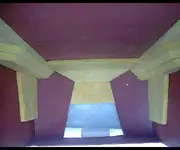
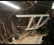
Ok, now once i had the basic model, I decided to paint the interior in a constrasting color to the 703, so it would stand out. I chose a red PRIMER, as it sealed the cardboard as well as imitated a flat paint in a room. This is NOT the color I'll be using in the real room though. ACK! red primer is not my color of choice. Actually the painted areas that will be seen will be a metalic paint. Very cool.
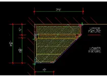
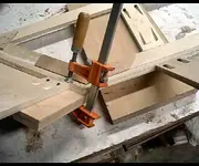
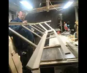
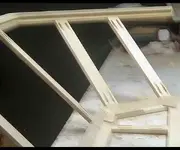
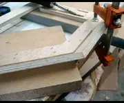
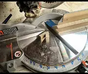
Anyway, after I painted it, then I started figuring out a basic "superchunk" layout, and figured the materals it would take. Problem was, once I had it built, the standard superchunk layout didn't really fit my idea of the visual concept in my head. This is when I decided to work on the area between the soffets. Man, I have the REAL framing for the soffits built, but laying out a miniture version took some head scrating to get the angles. Took an hour to lay em out, cut and gluing in place. Once I had them, the model really started to take shape. Then I did the rear angled entrance door wall, and the closet, and the opposite storage door wall. Even had doors that opened, by cutting the foam boar on the hinge side, only slightly through, then bent the door outward. Worked great ;D Well, on to the soffet area. Now, I have a CAD drawing of a longitudinal section through the room. From this drawing, I worked out a sloped area from halfway up the wall, to the "cloud". But to put a panel of fiberglass that fit the soffet angles.....man what a brain burner. But I finally got it and now for the superchunks. I put on my thinking cap, and went into "non linea"r thinking mode Thats when it dawned on me. Instead of making the standard superchunk, why not use LINEAR panels to build up a superchunk. One of the problems this solves, is how to die the superchunk into the soffets, and also allow for the doors at the rear of the room to open, while still maintaining a visual concept that I had in mind. VOILA!! It dawned on me again. COMPOUND MITERS! 8) What a pain in the ass though. Each cut took cranking the blade on the table saw to 45 degrees and back. More or less like the compound miters when installing CROWN MOULDINGS. Which is where this idea came from. The superchunks are nothing more than Crown mouldings in layers, just like you build up a large crown moulding.
Well, folks I'm outa time. I don't know how many links I can post in one post, but I'll start with all of them and see if it works. If not, I'll have to post the rest of what won't tonight. Ok, later guys
Here is the scaled version of the full panels in my truck.
http://Stingrayproductions.net/GIFs/RMFstudio/Modelpics/insulation3.jpg
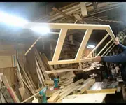
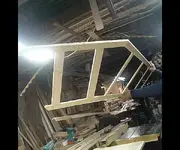
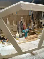
Here is the plain model.
http://Stingrayproductions.net/GIFs/RMFstudio/Modelpics/form.jpg
And heres the rest.
http://Stingrayproductions.net/GIFs/RMFstudio/Modelpics/form2.jpg
http://Stingrayproductions.net/GIFs/RMFstudio/Modelpics/form3.jpg
http://Stingrayproductions.net/GIFs/RMFstudio/Modelpics/form4.jpg
http://Stingrayproductions.net/GIFs/RMFstudio/Modelpics/form5.jpg
http://Stingrayproductions.net/GIFs/RMFstudio/Modelpics/form6.jpg
http://Stingrayproductions.net/GIFs/RMFstudio/Modelpics/form8.jpg
http://Stingrayproductions.net/GIFs/RMFstudio/Modelpics/insulation.jpg
http://Stingrayproductions.net/GIFs/RMFstudio/Modelpics/insulation2.jpg
http://Stingrayproductions.net/GIFs/RMFstudio/Modelpics/insulation3.jpg
http://Stingrayproductions.net/GIFs/RMFstudio/Modelpics/insulation4.jpg
http://Stingrayproductions.net/GIFs/RMFstudio/Modelpics/superchunkmodel1.jpg
http://Stingrayproductions.net/GIFs/RMFstudio/Modelpics/superchunkmodel2.jpg
http://Stingrayproductions.net/GIFs/RMFstudio/Modelpics/superchunkmodel3.jpg
http://Stingrayproductions.net/GIFs/RMFstudio/Modelpics/superchunkmodel4.jpg
http://Stingrayproductions.net/GIFs/RMFstudio/Modelpics/superchunkmodel5.jpg
http://Stingrayproductions.net/GIFs/RMFstudio/Modelpics/superchunkmodel6.jpg
http://Stingrayproductions.net/GIFs/RMFstudio/Modelpics/model1.jpg
http://Stingrayproductions.net/GIFs/RMFstudio/Modelpics/model2.jpg
http://Stingrayproductions.net/GIFs/RMFstudio/Modelpics/model3.jpg
http://Stingrayproductions.net/GIFs/RMFstudio/Modelpics/model5.jpg
http://Stingrayproductions.net/GIFs/RMFstudio/Modelpics/model6.jpg
http://Stingrayproductions.net/GIFs/RMFstudio/Modelpics/model8.jpg
http://Stingrayproductions.net/GIFs/RMFstudio/Modelpics/model9.jpg
http://Stingrayproductions.net/GIFs/RMFstudio/Modelpics/model10.jpg
http://Stingrayproductions.net/GIFs/RMFstudio/Modelpics/model11.jpg
Hope this works.
fitZ
I recently picked up these panels.
http://Stingrayproductions.net/GIFs/RMFstudio/Modelpics/insulation5.jpg
Ok guys, the point of this post is to illustrate my latest project. Namely, to utilize the materials I have to their best advantage. Once I had the materals, then I began building a fullscale cardboard "mockup" of one 24"x 72" x 4" thick panel, used across a wall/cieling corner. Trouble was, it was difficult to relocate it, as well as visualize what it is I REALLY wanted this to look like in the studio. Not only that, because of the geometry of my room, there are no wall/wall corners to utilize "superchunks", except at the rear closet, which is the point of my another upcoming thread titled "Rear Wall Options". And I've decided to use the closet for a Skyline diffuser, although there are areas that could be filled with 703, but at this time, I'm more interested in using what I have for the rest of the room. The other problem was DESIGN. Folks, I've been a designer for many years as well as a CAD detailer/draftsman. And for the last two years I tried to visualize what it was I wanted in the way of "treatment", at the front, sidewalls, and cieling. For four years I've been fortunate enough to run across forums such as this one, whereby I've been able to grasp a few concepts for treating a room acoustically. But visualizing something in 3D in Autocad leaves a lot to be desired. I even tried a few 3d programs suich as Sketchup and Rinocerous, but haven't found a way to convert the file format extention to something i can post on the net. Even then, the 3D programs really DIDN'T allow for visualizing a space from INSIDE the space. At least from what I knew I wanted to see. Thats when the idea to build an actual model, instead of a virtual model. Hence this post.
The first thing I had to determine was scale. Since I had about 20 rigid fiberglass cieling tiles, and they were 1/2" thick, I determined I could scale the 1/2" to equal a 4" thick panel of 703. This works out to 1 1/2"=12". Perfect size. Once I had my scale, I gathered a bunch of materials. Since my wife sells on ebay, we have a ton of packing materials to chose from, which is basically cardboard for boxes, as I have to make boxes to fit merchandize all the time. Another material is "foam board", which is used at Picture framing shops for mounting pictures for framing. I get a ton of their cutoffs for free. I used these for various walls and doors and the soffets in the model. One of the tools I use is a glue gun. Works great on cardboard. I buy glue sticks in bulk at Walfart. Another tool is my tablesaw, which works great for cutting the various materials, and especially for COMPOUND MITER cuts, as you will see in the pics.
So, now I started laying out the floor plan to get my scaled floor, walls and cieling pieces cut. But then it dawned on me, how or from what area was I going to be able to see the interior. Since the front wall/soffets, side walls, and cieling, I decided to remove an area in the floor, and an area between the soffets, and part of the back wall where the closet is. This allows for inserting my HEAD ;D, up through the floor of the model to visualize the room. Not only that, but I could insert a camera and get a real "view" of the room at different angles. Worked great. Although my wife laughed her
ass off when she saw me with my head in the model. Looked like some kind of wierd hat.
Ok, now once i had the basic model, I decided to paint the interior in a constrasting color to the 703, so it would stand out. I chose a red PRIMER, as it sealed the cardboard as well as imitated a flat paint in a room. This is NOT the color I'll be using in the real room though. ACK! red primer is not my color of choice. Actually the painted areas that will be seen will be a metalic paint. Very cool.
Anyway, after I painted it, then I started figuring out a basic "superchunk" layout, and figured the materals it would take. Problem was, once I had it built, the standard superchunk layout didn't really fit my idea of the visual concept in my head. This is when I decided to work on the area between the soffets. Man, I have the REAL framing for the soffits built, but laying out a miniture version took some head scrating to get the angles. Took an hour to lay em out, cut and gluing in place. Once I had them, the model really started to take shape. Then I did the rear angled entrance door wall, and the closet, and the opposite storage door wall. Even had doors that opened, by cutting the foam boar on the hinge side, only slightly through, then bent the door outward. Worked great ;D Well, on to the soffet area. Now, I have a CAD drawing of a longitudinal section through the room. From this drawing, I worked out a sloped area from halfway up the wall, to the "cloud". But to put a panel of fiberglass that fit the soffet angles.....man what a brain burner. But I finally got it and now for the superchunks. I put on my thinking cap, and went into "non linea"r thinking mode Thats when it dawned on me. Instead of making the standard superchunk, why not use LINEAR panels to build up a superchunk. One of the problems this solves, is how to die the superchunk into the soffets, and also allow for the doors at the rear of the room to open, while still maintaining a visual concept that I had in mind. VOILA!! It dawned on me again. COMPOUND MITERS!
8) What a pain in the ass though. Each cut took cranking the blade on the table saw to 45 degrees and back. More or less like the compound miters when installing CROWN MOULDINGS. Which is where this idea came from. The superchunks are nothing more than Crown mouldings in layers, just like you build up a large crown moulding. Well, folks I'm outa time. I don't know how many links I can post in one post, but I'll start with all of them and see if it works. If not, I'll have to post the rest of what won't tonight. Ok, later guys
Here is the scaled version of the full panels in my truck.
http://Stingrayproductions.net/GIFs/RMFstudio/Modelpics/insulation3.jpg
Here is the plain model.
http://Stingrayproductions.net/GIFs/RMFstudio/Modelpics/form.jpg
And heres the rest.
http://Stingrayproductions.net/GIFs/RMFstudio/Modelpics/form2.jpg
http://Stingrayproductions.net/GIFs/RMFstudio/Modelpics/form3.jpg
http://Stingrayproductions.net/GIFs/RMFstudio/Modelpics/form4.jpg
http://Stingrayproductions.net/GIFs/RMFstudio/Modelpics/form5.jpg
http://Stingrayproductions.net/GIFs/RMFstudio/Modelpics/form6.jpg
http://Stingrayproductions.net/GIFs/RMFstudio/Modelpics/form8.jpg
http://Stingrayproductions.net/GIFs/RMFstudio/Modelpics/insulation.jpg
http://Stingrayproductions.net/GIFs/RMFstudio/Modelpics/insulation2.jpg
http://Stingrayproductions.net/GIFs/RMFstudio/Modelpics/insulation3.jpg
http://Stingrayproductions.net/GIFs/RMFstudio/Modelpics/insulation4.jpg
http://Stingrayproductions.net/GIFs/RMFstudio/Modelpics/superchunkmodel1.jpg
http://Stingrayproductions.net/GIFs/RMFstudio/Modelpics/superchunkmodel2.jpg
http://Stingrayproductions.net/GIFs/RMFstudio/Modelpics/superchunkmodel3.jpg
http://Stingrayproductions.net/GIFs/RMFstudio/Modelpics/superchunkmodel4.jpg
http://Stingrayproductions.net/GIFs/RMFstudio/Modelpics/superchunkmodel5.jpg
http://Stingrayproductions.net/GIFs/RMFstudio/Modelpics/superchunkmodel6.jpg
http://Stingrayproductions.net/GIFs/RMFstudio/Modelpics/model1.jpg
http://Stingrayproductions.net/GIFs/RMFstudio/Modelpics/model2.jpg
http://Stingrayproductions.net/GIFs/RMFstudio/Modelpics/model3.jpg
http://Stingrayproductions.net/GIFs/RMFstudio/Modelpics/model5.jpg
http://Stingrayproductions.net/GIFs/RMFstudio/Modelpics/model6.jpg
http://Stingrayproductions.net/GIFs/RMFstudio/Modelpics/model8.jpg
http://Stingrayproductions.net/GIFs/RMFstudio/Modelpics/model9.jpg
http://Stingrayproductions.net/GIFs/RMFstudio/Modelpics/model10.jpg
http://Stingrayproductions.net/GIFs/RMFstudio/Modelpics/model11.jpg
Hope this works.
fitZ
 :rolleyes:")
 So, talk to you soon. Later guys.
")
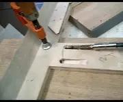
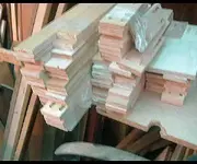
 Did the boring in one tedious exercise. Got a blister on my hand from pulling the handle twice for each manuver. Fuck. Took an hour and a half to bore these pieces, which are the spacer stiles.
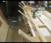
 Thats what will really make it look like a "cockpit"
")