elenore19
Slowing becoming un-noob.
Here's a picture. (Not the best photo, but it's the best I could get...)
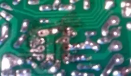
I destroyed the "silver stuff" around some of the holes thinking I needed to remove that to get my component to work (I soldered and resoldered the part at least 10 times with no luck before doing this...this was my "logical" next step...).
Is there a way to repair this? Maybe just solder the part directly to the other wires on that same pad.
Thanks so much for the help. I know, I'm an idiot for this...Live and learn.
Feel free to correct me on whatever terms I'm using wrong.
Thanks again in advance.
[size=+3]UPDATE!
I'm worried I ruined some components because of too much heat. Is there a way to check if a component works or not? If not, what are the odds I broke a component with heat? I have a little 10 watt soldering iron. Usually takes a few seconds to melt the solder.
So how do I find the traces on the other side of the board? I assume that the traces on the green side are the lighter green lines running from component to component.
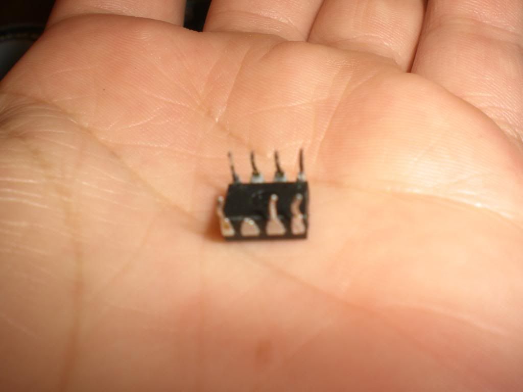
I checked the continuity between all the traces on the green side and found that all of them checked out. INCLUDING the chip I have installed. (The old one...here's a picture of the new one...Broken?)
Is this reparable at all??
If there is a weak signal between one component and another could that mean somehow they are connected shorting out the pedal, or something along those lines? There was one spot like that, and by cleaning up some of the black stuff you see the connection went away[size=+1]I JUST TESTED AGAIN...Somehow it didn't work before, and now there is still a signal between All of the circled parts.
See the red one that doesn't have any blue around it...HOW does that get signal to other parts? There is no green tracer that I can see from it to anywhere, and the otherside is brown/cream colored and I can't see any tracers that I'm aware of.
Blue is the one that had a little continuity and was fixed by cleaning a little off the board.
Red is the one I can't get rid of. Whether or not I Should be trying to get rid of it, I don't know, but cleaning a little hasn't helped.

What's the best way to clean that black crap off of there?
Here's where you see the destruction that is my soldering...
That's all for now. Small novel, hopefully someone will read this and shine some light on my situation.
I destroyed the "silver stuff" around some of the holes thinking I needed to remove that to get my component to work (I soldered and resoldered the part at least 10 times with no luck before doing this...this was my "logical" next step...).
Is there a way to repair this? Maybe just solder the part directly to the other wires on that same pad.
Thanks so much for the help. I know, I'm an idiot for this...Live and learn.
Feel free to correct me on whatever terms I'm using wrong.
Thanks again in advance.
[size=+3]UPDATE!
I have my questions in bold if you want to just skim this lengthy thing.A 2 sided pc board will have traces on both sides, although not necessarily any solder pads on the top side, since usually everything is top mounted and soldered underneath. Generally, simple circuits are 1 sided, more complex circuits are 2 sided.
You can bend the component leads like one time - back and forth and they can break off. Use the socket....")
I'm worried I ruined some components because of too much heat. Is there a way to check if a component works or not? If not, what are the odds I broke a component with heat? I have a little 10 watt soldering iron. Usually takes a few seconds to melt the solder.
So how do I find the traces on the other side of the board? I assume that the traces on the green side are the lighter green lines running from component to component.
I checked the continuity between all the traces on the green side and found that all of them checked out. INCLUDING the chip I have installed. (The old one...here's a picture of the new one...Broken?)
Is this reparable at all??
If there is a weak signal between one component and another could that mean somehow they are connected shorting out the pedal, or something along those lines? There was one spot like that, and by cleaning up some of the black stuff you see the connection went away[size=+1]I JUST TESTED AGAIN...Somehow it didn't work before, and now there is still a signal between All of the circled parts.
See the red one that doesn't have any blue around it...HOW does that get signal to other parts? There is no green tracer that I can see from it to anywhere, and the otherside is brown/cream colored and I can't see any tracers that I'm aware of.
Blue is the one that had a little continuity and was fixed by cleaning a little off the board.
Red is the one I can't get rid of. Whether or not I Should be trying to get rid of it, I don't know, but cleaning a little hasn't helped.
What's the best way to clean that black crap off of there?
Here's where you see the destruction that is my soldering...
That's all for now. Small novel, hopefully someone will read this and shine some light on my situation.
Attachments
Last edited:
