Mackie 16x8 8 bus mixer - meter not working properly

  • Thread starter Thread starter fgonza2
  • Start date Start date
F

fgonza2

New member
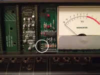
Hi, i bought this item used off ebay. major functions seem ok, but the meter bridge is not working as expected. There is a switch to select from tape/source, so you monitor either the channel after the fader or the tape inputs. You press the switch and the LED comes on and off, but the function doesn't change. It is ALWAYS monitoring the tape inputs, not the channel (post fader). Has anyone seen this ? any ideas on what to check/where ?

thanks
 
found the problem :)

is anyone familiar with these gold connectors? they were lost. so i replaced that and voila, now the channel/source switch works. good to go :)
 

Attachments

  • photo-2.webp
    photo-2.webp
    35.5 KB · Views: 814
Last edited:
Replace VU lamps on mackie 8 bus meter bridge

Also i just replaced the VU meter lamps as well, in case someone needs it, as the factory ones go out too easy. THis is an easy repair with parts from radio shack.

First, get a proper lamp, they are 18V lamps. So i got a 12V 50mA lamp from RS

photo 1.webp


I used a 150 ohm resistor in series to get the voltage down (i calculated it to hit 10.5V for the lamp so you get more life out of it).

Then use a couple of cereal bag clamps to hold the plastic covers of the VUs then just solder it and position properly, leave some space in the resistor terminal.

photo 2.webp


On the left side you can see the original lamp, on the right the new one with the resistor. IT has to be a 1/2 watt resistor btw.

Just posting this in case someone runs into this problem.
 
How did you remove the cover from the meter bridge to get to the vu meters? I'm having trouble getting mine disasembled. Thanks
 
How did you remove the cover from the meter bridge to get to the vu meters? I'm having trouble getting mine disasembled. Thanks

MadDog, it's pretty simple:

1. Remove screws from the right end cap (by the VU meters).

2. Pull on the Tape/Source button cover. It's just held in with friction.

3. Carefully slide out the plastic cover and place on a soft surface.


If you remove the left end cap as well (as I did the first time), there might be a small spacer piece that falls out. This goes back in the same groove as the circuit board. Freaked me out when that happened because it's made from circuit board material.
 
You did not say what the resistors were in the first photo.
 
Back
Top